


30
Section VII – Test Procedure
A. Test Conditions
FLUID MEDIUM: SAE 10W meeting API service classification
MS or equivalent.
FLUID TEMPERATURE: 120°F ±5°F at pump outlet.
Fluid entering the pump must be maintained below a
maximum contamination limit of class four according to
NAS1638.
B. Preliminary Check
1. Rotate the drive shaft through one complete revolu-
tion. The shaft must rotate with less than 8 N.m (6 lbf. ft.)
torque and be free without evidence of binding.
2. Direction of rotation by the model code stamped into
the edge of the mounting flange. See Table 2 for definition of
model code variables.
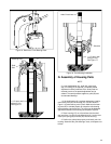
C. Preliminary Set–Up
NOTE
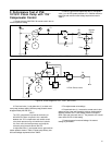
Install unit as shown in test circuit diagram with case
drain up. Use the correct circuit diagram for the unit:
Figure 23–PVE 19/21 (G)–*–**–C/CG–1*. Figure
24–PVE 19/21 (G)–*–**–CV/CVP/CVPC units.
1. Maintain 0–10 Psig at pump inlet.
2. Fill pump housing with system fluid and connect case
drain line.
3. During test, case pressure must not exceed 15 Psig.
4. Pressure differential between case and inlet must be 0–5
psid unless otherwise indicated. (Note: A special test for maxi-
mum differential pressure between case and inlet will be
performed later.)
D. Performance Test
1. Open globe valves V1 and V2.
2. Set load valve one (1) to minimum pressure. If the unit
has an auxiliary gear pump, set load valve two (2) to minimum
pressure.
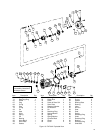
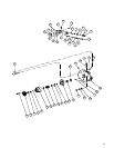
3. Turn compensator plug (9), Figure 13, clockwise until
seated.
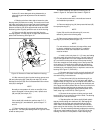
4. Jog the unit under test until prime occurs. If the unit has
an auxiliary gear pump, both pumps must prime before proceed-
ing.
5. Operate the unit at 1200 RPM and 100 Psig until all air is
expelled from the test circuit.
6. Piston pump case leakage must exceed 10cc/minute as
read on flow rater Q2.
E. Performance Test of Piston Pump
with “C” Compensator Control
1. Adjust load valve one (1) and globe valve one (V1), Fig-
ure 23, for exactly 100 Psig as read at gauge P1. The unit must
meet the following requirements at full stroke, and 1200 RPM.
See Table 4. Record the flows obtained.
2. Close globe valve one (V1) and readjust load valve one (1)
to system pressure shown in Table 5. Read Psig at gauge P1.
3. Check delivery loss and case leakage as follows. (See
Table 5.)
4. Open globe valve one (V1) and load valve (1).
5. Back off compensator adjustment screw until approxi-
mately 0.060 inches of threads are exposed. Close load valve
one (1) and globe valve one (V1). The pressure as read at
gauge P1 must not exceed 250 Psig.
6. Adjust the compensator screw to retract the yoke to mini-
mum stroke position at Table 6 pressures. Case drain leakage
not to exceed two (2.0) USGPM. Pressure fluctuations must not
exceed 50 Psig. Rapid globe valve (V1) movement from open to
closed must not produce yoke hunting.
7. With the pump operating at cutoff, close the case drain
port slowly (globe valve V2) while observing gauge P2. Pressure
differential P2–P3 must be 6–12 Psid with globe valve V2 fully
closed. If pressure starts to exceed 12 Psid while closing globe
valve V2, the internal check valve is malfunctioning. DO NOT
close globe valve V2 further; return to the open condition and
repair the malfunction.
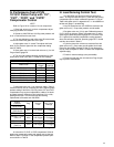
Model PVE19
Delivery
Table 4. Maximum flow and maximum case leakage
at 100 Psig.
PVE21
12.5-13.5
USgpm
13.75-14.85
USgpm
800cc/Min.800cc/Min.
Max. Case
Leakage
100 PSI System Pressure
PVE12
620cc/Min.
7.5-8.4
USgpm
3000 Psig System
Pressure
Max. Delivery
Table 5. Delivery loss and maximum allowable
leakage at indicated Psig.
2700 Psig System
Pressure
PVE12
1.50 USgpm
1.15
USgpm
Loss
Max.Case
Leakage
PVE21
1.45 USgpm
PVE19
1.12
USgpm
1.50
USgpm
1.45
USgpm
8. With load valve one (1) set to pressure noted in Table 6
and globe valve V1 fully closed, the pressure at P1 must return
within 50 Psig of initial setting.
9. Drill and lockwire the compensator adjusting screw (9)
Figure 13.
10. Check for signs of external leakage (none permissible)
including shaft seal.
11. Remove power, remove unit from stand, drain case,
then plug openings to prevent dirt from entering the unit. This
completes test and adjustment of the piston pump and ”C”
compensator S/A.
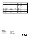
Model Number
PVE12/19*-*-**-C10
PVE21*-*-**-C10
Table 6. Final compensator pressure setting.
Lockwire Pressure Setting
Yes
Yes
3000 Psig
2700 Psig