


32
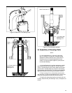
G. Performance Test of PVE
12/19/21 Piston Pump with “CV”,
“CVP”, “CVPC” and “CVPD”
Compensator Control
NOTE
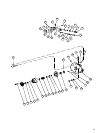
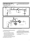
Refer to Figure 24 for location of circuit components.
1. Open load valve one (1) and turn compensator adjust-
ment plug clockwise until seated.
2. Operate at 1200 RPM and 100 Psig outlet pressure until
all air is removed from the test circuit.
3. The case leakage as read at flow rater Q2 must exceed
10cc/minute. Make sure globe valve V2 is open.
4. Adjust globe valve V1 closed. Then adjust relief valve
three (3) to a pressure higher than the compensator setting
noted in Table 8.
5. Open globe valve V1 and set load valve one (1) for 100
Psig as read at gauge P2.
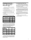
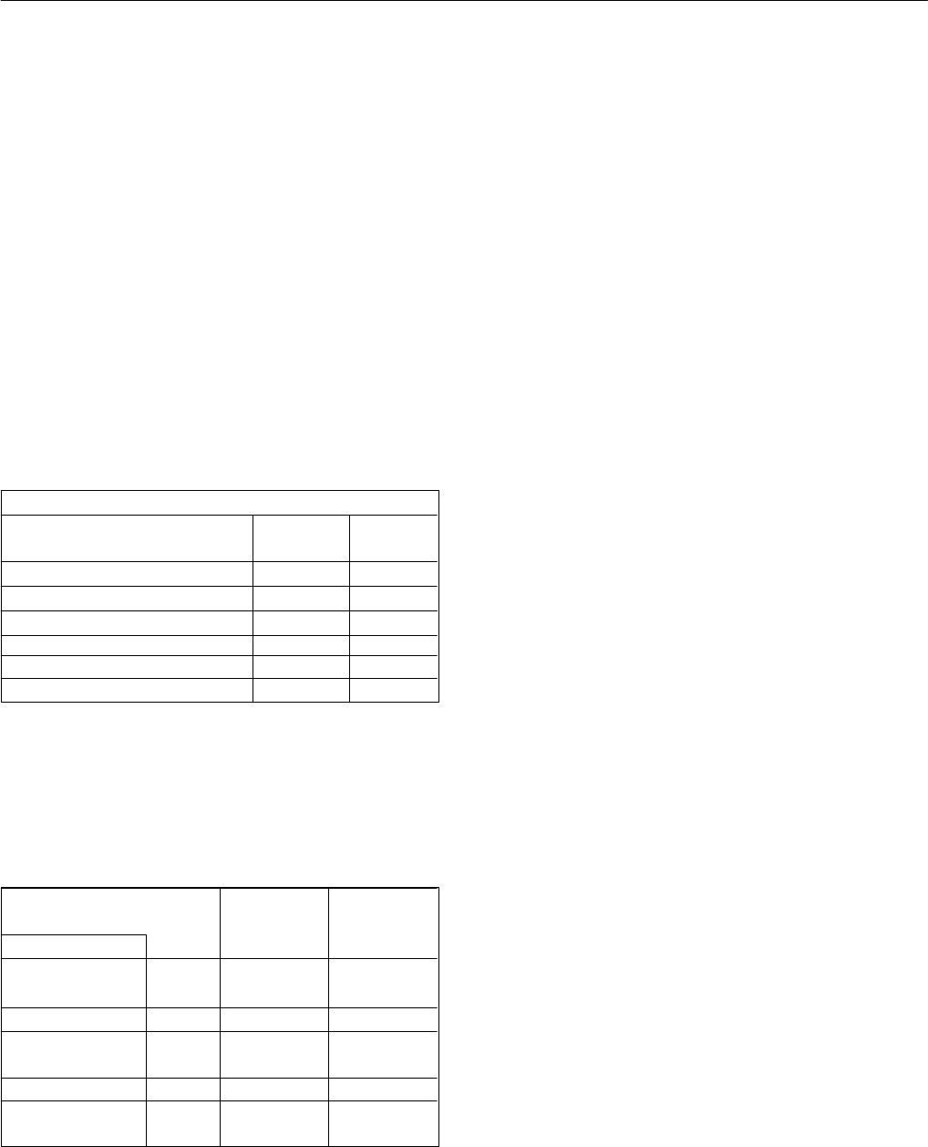
6. The unit must meet the following requirements at 1200
RPM and full stroke. See Table 7. Record the flow readings.
Model Code
Delivery
USgpm
Table 7. Maximum delivery and maximum case leakage.
Max. Case
Leakage
100 Psig System Pressure
1020cc/min
1020cc/min
800cc/min
1020cc/min
800cc/min
1020cc/min
11.5
11.5
12.5-13.5
12.45-13.45
13.75-14.85
13.7-14.8
PVE12*-*-**-CV-10
PVE12*-*-**CVP/CVP-11/CVPD
PVE19*-*-**-CV-10
PVE19*-*-**CVP/CVP-12/CVPD
PVE21*-*-**-CV-10
PVE21*-*-**CVP/CVPC-12/CVPD
7. Adjust load valve one (1) for pressures noted in Table 8.
Check the delivery loss by comparing flow at the highest system
pressure setting to the flow at 100 Psig. (Note: CVP and CVPC
compensators may require an adjustment to obtain a full stroke
at system pressure.) Make sure relief valve three (3) is not by-
passing fluid to tank. The unit must meet the following
requirements at full stroke and 1200 RPM.
Model Code
Delivery
Loss
Table 8. Delivery loss and maximum case leakage.
Max. Case
Leakage
System
Pressure
Psig
3000
2700
3000
2700
1.15 USgpm
3000 1.12 USgpm
PVE12*-*-**-CVP/
CVPC/CVPD
PVE19*-*-**-CV-10
PVE19*-*-**-CVP/
CVPC-12
PVE21*-*-**-CV-10
PVE21*-*-**-CVP/
CVPC-12
1.5 USgpm 1.45 USgpm
1.65 USgpm 1.70 USgpm
1.5 USgpm 1.45 USgpm
1.65 USgpm 1.70 USgpm
8. Units with a CV, CVP, or CVPC compensator S/A shall
perform the compensator control and integral case to inlet test.
Refer to steps F1 through F6. Set compensator pressure pres-
sure as shown in Table 6.
H. Load Sensing Control Test
1. At 1200 RPM, load the pump outlet port pressure to
2000 ± 50 Psig with load valve one (1). Shim the load sensing
compensator spool to obtain a differential pressure P1–P2 per
Table 9 with globe valve V1 adjusted for 6.5 ± .25 USGPM outĆ
let flow and gauge P1 at 2000 Psig.
2. Vary the outlet flow from 0.5 USGPM to maximum with
globe valve one (1). Pump outlet pressure must be stable.
3. Set globe valve one (1) fully open. Differential pressure
P2–P1 will be at minimum. Slowly close globe valve V1 while
observing the differential pressure gauge P2–P1 and flow rater
Q1. A point will be reached (compensator cracking pressure)
where flow will start to diminish; pressure gauge P2–P1 should
read the value noted in Table 9.
4. Cycle the pump from minimum to maximum flow with
globe valve one (1), pump outlet must be stable. At minimum
pump flow, the standby pressure P2 after P1 has decayed to
zero (0) must correspond to Table 9. Lockwire the compensator
adjustment plug.
5. Check for external leakage (none permissible).
6. Disconnect and drain the unit under test. Plug all open-
ings to prevent contamination.