


28
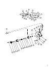
H. Disassembly of Valve Block
1. Do not disassemble check valve parts (64) through
(66), unless action of the valve indicates a problem. Check
the valve action with a pencil or a screwdriver. Press the
check valve in against the spring, it should return and hold
firm against the seat. If the check valve is defective, remove
and replace the complete assembly. Press new seat (64)
flush with face of valve block. DO NOT scratch the face of
valve block (26).
2. Remove parts (67) through (73) from valve block (26).
NOTE
If bearing (32) was defective, perform the following
step.
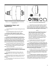
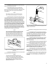
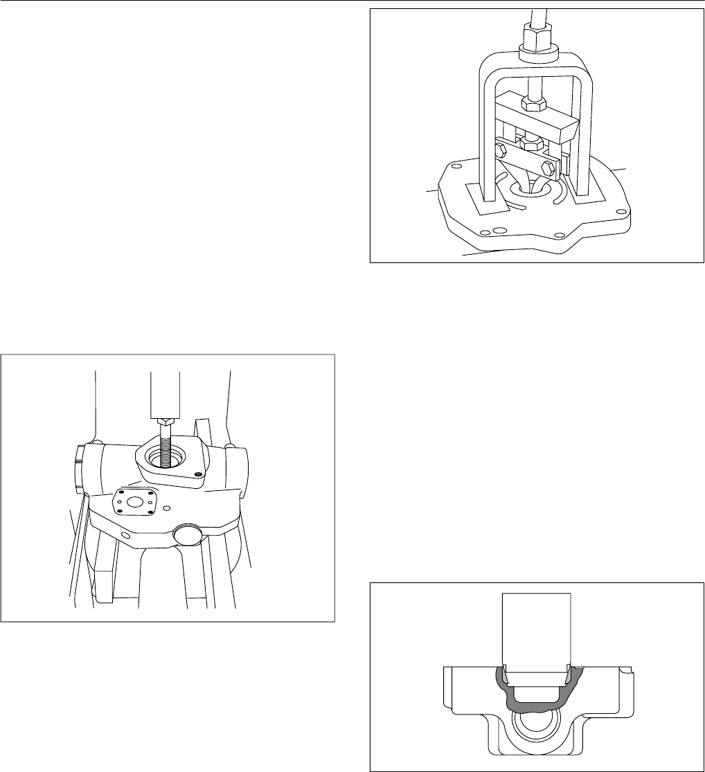
3. For PVE19/21, remove bearing race (63) from valve
block (36). The PVE12 roller bearing is in the valve block.
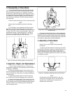
Refer to Figure 20 for removal information and use tool shown
in Figure 10 for PVE**G units. Use tool shown in Figure 10a
and procedure shown in Figure 20a for PVE** units with a
blind hole in valve block (26). BE CAREFUL not to scratch
face of the valve block during removal of the race.
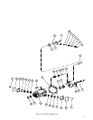
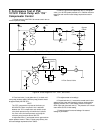
Figure 20. Removal of Bearing Race from Valve Block.
I. Inspection, Repair, and Replacement
1. Clean all parts and place them on a clean sheet of
Kraft paper for inspection. Follow general procedure noted in
paragraph VI. GENERAL.
2. Inspect the threaded plugs for worn corners on the
hex head, stripped threads and burrs in the O–Ring groove.
Use an India stone to remove burrs. If threads are defective,
replace the plug.
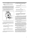
3. Inspect compensator piston rod (73) for nicks and
burrs. Remove burrs and sharp edges with an India stone.
4. Inspect compensator piston (72) for wear at the area
of yoke contact. The compensator piston and the piston rod
are a close tolerance fit and must assemble together without
evidence of wear or bind. Rotate the piston through 360°
when checking for bind.
Figure 20a. Removal of Bearing Race from valve Block
with Blind Hole.
5. Inspect valve block (26) for burrs, nicks, plugged body
passages, flatness of the pump wafer plate area and porosity.
Inspect check valve seat (64). Make sure the seat is tight with-
in the valve block and does not protrude above the valve block
face. Repair or replace the valve block if defective.
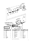
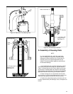
J. Assembly of Valve Block
NOTE
Refer to Figure 13 during the following assembly
procedures.
1. If bearing (32) was defective and bearing race (63 for
the PVE19/21) has been removed, a new bearing race must
be installed into the valve block. Refer to Figure 21 and
press a new bearing race in place with an arbor press. The
bearing race must bottom against the shoulder of valve block
at completion of press.
Figure 21. Installation of Bearing Race into Valve Block.
NOTE
Check flatness of the valve block face in the area
around each locating pin hole (31) and at bolt open-
ings (25). Use an India stone to remove burrs or
raised metal in these areas.