


23
3. Inspect spring (8) and (16) for wear and parallelism.
Spring ends must be parallel. Replace if spring is warped or
wear is evident.
4. Inspect seat (9) for wear in the area of spool contact.
5. Inspect spool (10) for excessive wear, galling,
scratches, etc. If scratches exist across the spool land,
replace the spool and inspect the body bore. Rotate the spool
while moving in and out of the bore to check the binding.
Binding cannot be tolerated. If binding is evident, use an India
stone to break the sharp edges of the balancing grooves. Use
500 grit paper lightly on the outer surface of the spool. Clean in
solvent and lubricate, then try the bind test again. If bonding
persists, replace the spool and/or body.
6. Inspect the screws for damaged threads. Replace all
damaged threads. Replace all damaged screws.
NOTE
The following step pertains to the CVP or CVPC
compensator S/A.
7. Inspect the load sensing section of the CVP compen-
sator as follows:
a. Inspect the load sensing section of the CVP com-
pensator if wear is evident. Clean up burrs with an India stone.
b. If wear is evident, replace the part. Note: After
assembly the compensator must be readjusted to the correct
pressure. Refer to the test procedure Section VII for instruc-
tions on compensator adjustment.
c. Discard adjusting screw (14). Check seat (17) and
spool (18) for wear. Refer to step B.5 for procedure when
checking the pressure limiting spool.
d. Inspect body S/A (11) bores for scratches. Make
sure the orifice plug (20) opening is clear.
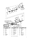
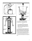
D. Assembly of Compensator
Replace the gaskets and O-Rings removed from the unit
with those supplied in the seal kit. DO NOT use grease to
hold the seals in place. Use a viscosity improver (STP or
equivalent). Flood all parts with system fluid to provide initial
lubrication and prevent seizure. Assembly of the parts will be
in the reverse numerical sequence. Special procedures are
included in the following steps.
NOTE
The following step refers to the CVP or CVPC
compensator only.
1. Install parts (24) through (22) into body (11).
a. Install parts (20), (19), and spool (18). Make certain
the spool does not bind or hang up in the body bore.
b. Assemble parts (17) through (15) together. Insert
the assembled parts (seat first) into compensator body (11).
Assemble with spool bores in vertical position to prevent seat
from falling into cross port. Visually observe proper assembly
through load sensing port. The seat must rest against com-
pensator spool (18) at completion of assembly.
c. Thread adj. screw (14) into body (11) bore until top
of adj. screw is .065 below body (11) surface.
d. Install O-Ring (13) over plug (12) and thread plug
(12) into compensator body (11).
2. Install plug (24) into the “C” and “CV” compensator
bodies. Plugs were installed into the “CVP” compensator
body during the preceding step.
3. Install parts (10) through (3) into compensator body
(11). Make certain the spool (10) does not bind within the
bore. Refer to procedure established in step B.5 for further
information. Lockwire and seal (4) will be installed during test
procedure section VII.
4. Install gasket (2) in place in the face of compensator
body (11). Cover the compensator body with clean Kraft pa-
per and set aside for final assembly of the pump.
NOTE
Readjustment of the pressure limiter and load
sensing compensators is required.
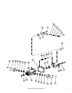
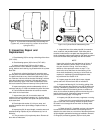
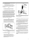
E. Removal and Disassembly of
Rotating Group
1. Remove the six screws (25) which hold pump housing
(27) to valve block (26).
2. Pull valve block (26) away from housing (27) then
discard gasket (30).
3. Remove wafer plate (28) and pins (29) from the valve
block set aside for inspection.
4. Remove bearing (32) and bearing spacer (33 on PVE
19/21 models) from the end of drive shaft (48).
5. Slide the rotating group from the pump housing. (Hold
the shoe plate with both hands during removal to prevent the
group from separating.)
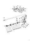
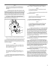
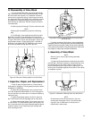
NOTE
The rotating group consists of a cylinder block S/A
(34), nine piston and shoe subassemblies (43), a shoe
plate (42), a spherical washer (41), three pins (39), and
a pin retainer (40).
CAUTION
The spring located within the cylinder block S/A is
under a high tension and can cause bodily harm if the
retaining ring is removed. See Figure 14 for
disassembly instructions.
6. Separate the rotating group components and set
aside for inspection. Use care when handling these close
tolerance parts to prevent burrs from forming.