


3
Section I – Introduction
A. Purpose Of Manual
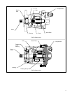
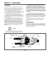
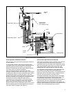
This manual describes operational characteristics and
overhaul information for the PVE12, 19(*) and the
PVE21(*)–** variable displacement piston pumps. The
information contained herein pertains to the latest design
series as listed in Table 1.
B. General Information
1. Related Publications - Service parts information
and installation dimensions are not contained in this
manual. The parts and installation drawings listed in
Table 1 are available from authorized distributors or sales
engineers.
Model
Series
Parts
Drawing
PVE12
PVE19
PVE21
Table 1.
Installation
Drawing
M-2853-G
322C
_____
M-2841-S
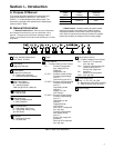
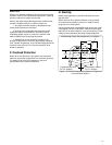
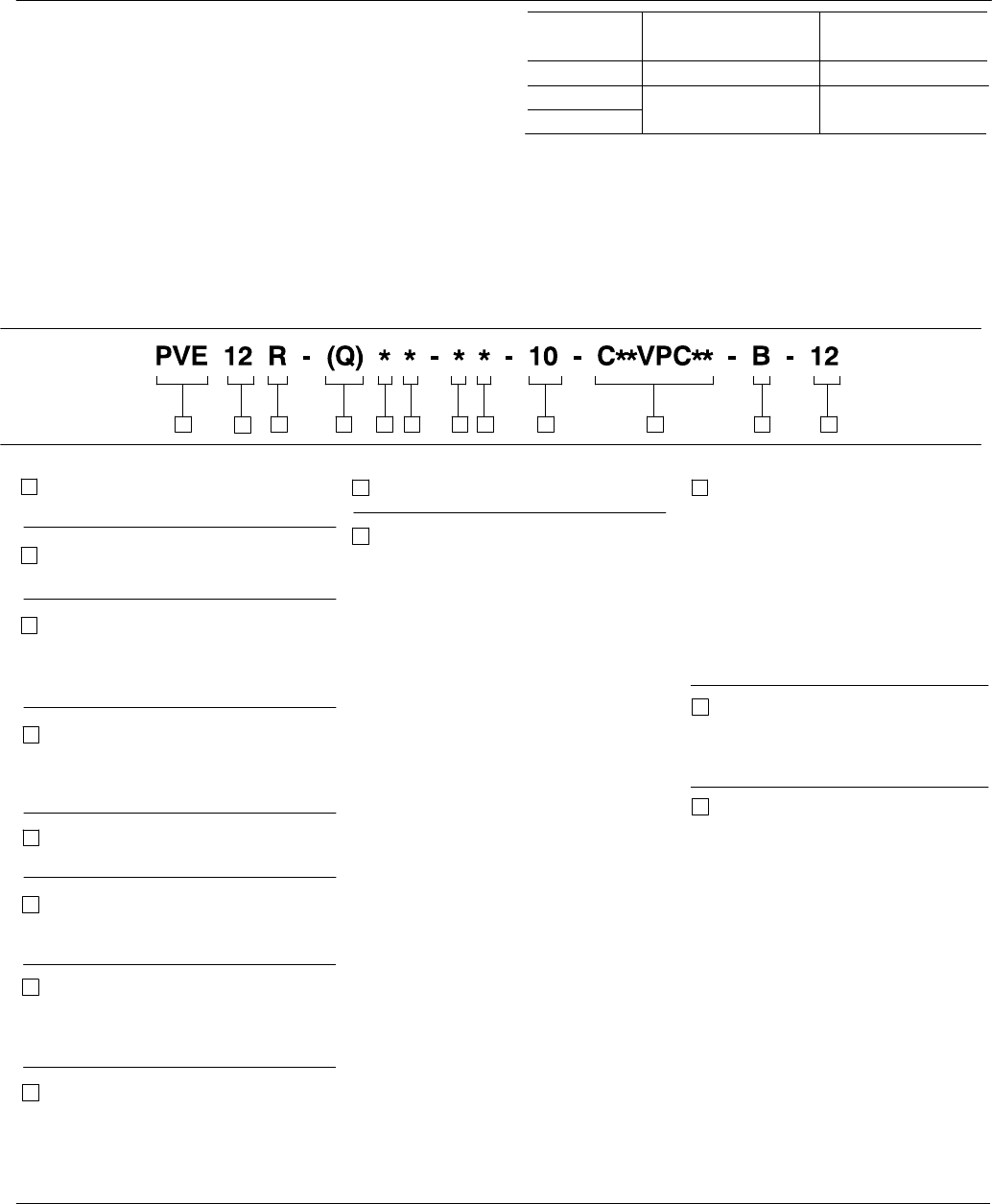
2. Model Codes - Variations within each basic model
series are covered in the model code. Table 2 shows a
complete breakdown of the model codes covering these
units. Service inquiries should always include the complete
model code number as stamped on the mounting flange.
Same as C** except with
max. adj. stop.
Pressure compensation with
remote control (see C**)
Electric dual range com-
pensation
Same as CD except with
max. adj. stop
Design
9
5
10
11
7
1
34561
2
2
3
Table 2. Model Code Breakdown
4
Flow Rating
USgpm @ 1800 rpm
87 9 10 11
6
Noise Level Rating
Blank – Standard Unit
Q – Industrial Quieter
1800 rpm @ 207 bar (3000 psi)
Pump, Variable Displacement,
Inline Piston, E-Series
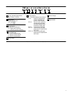
Control Options (Con’t)
(** = Pressure setting in tens of bars)
Control Bleed Down
Blank – C, CC, CG, CD, CCD
B – Bleed down orifice (CVP & CVPC)
P – Plug (no orifice) (CVP & CVPC)
Port Configuration
E – End ported, SAE O-ring
M – End ported, metric O-ring
(per ISO 6149)
Shaft Seal
S – Standard shaft seal
N – No shaft seal
Input Shaft Type
1 – SAE B Straight keyed
2 – SAE B Splined
8
Shaft Rotation
(Viewed from shaft end)
R – Right hand (clockwise)
L – Left hand (counterclockwise)
12
12
Control Design
CC** -
CG**-
CD -
CCD -
Mounting Flange
B – SAE B 2 bolt
10
Control Options
(** = Pressure setting in tens of bars)
C** –
C**VP** –
C**VPC** –
C**VPD** –
Pressure compensator
Max. setting 207 bar
(3000 psi)
Range 02-21 bar
Pressure & load sensing
Pressure compensating
(see C**)
Load sensing (see CV**)
Pressure and load sensing
Pressure compensating
(see C**)
Load setting 24 bar
(350 psi)
Range 17-31 bar
(251-450 psi)
Pressure & load sensing
Pressure compensating
(see C**)
Load setting 41 bar
(600 psi)
Range 32-45 bar
(451-650 psi)
Same as C** except with
max. adj. stop.
Pressure compensation
with remote control
(see C**)
Electric dual range com-
pensation
Same as CD except with
max. adj. stop