6
Section II – Description
A. General
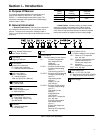
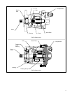
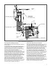
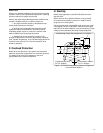
Assembly of a typical pump package is shown in Figure 1.
Six types of compensator subassemblies are used with the
PVE series pumps. Refer to Section III for principles of
operation. See Model Code for pressure settings.
1. Compensator (C), (Flat Cut-Off Type): A pump using
this compensator will maintain a constant load pressure for
all values of flow within the capacity of the pump.
2. Compensator (CG), (Remote Control Type): This
compensator is similar to the “C” type compensator except
the compensator is controlled by a remote hydraulic source
such as a relief valve.
3. Compensator (CV), (Load Sensing Type): A load
sensing compensator provides flow at a pressure equal to
that required by the load plus a constant value used as a
pressure drop across a metering valve. The pump will
change its flow with changes in size of the metering valve
orifice. The pump and compensator together provide a
constant flow source for the load, at a pressure established
by the requirements of the load, hence the title “Load
Sensing”.
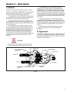
CAUTION
A relief valve must be provided in the external circuit
to prevent excessive pressure build up at the pump.
4. Compensator (CVP), (Load Sensing Pressure
Limiting Type): The CVP control is a combination of the
standard flat cut-off compensator (C) and the load sensing
compensator (CV). The load sensing compensator controls
flow to the load across an external valve orifice. If pressure
build–up exceeds the flat cut-off compensator setting, the flat
cut-off compensator overrides the load sensing compensator
and lowers the flow to prevent excessive pressure build-up
at the pump.
5. Compensator (CVPC), (Load Sensing Pressure
Limiting Type): This compensator is the same as the “CVP”
compensator except the load sensing spring is heavier. The
heavier spring provides a slightly higher pressure differential
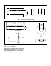
(160nP vs. 350nP) across the external valve orifice. See
Figure 5.
6. Compensator (CVPD), (Load Sensing, Pressure
Limiting Type): Same as “CVPC” except with higher
pressures.
B. Application
Pump ratings in USgpm as shown in the model coding are at
1800 rpm. For ratings at other speeds, methods of installa-
tion and other application information, contact an authorized
distributor or sales engineer.
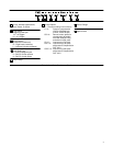
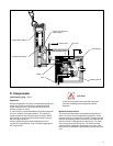
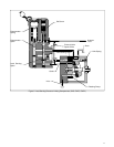
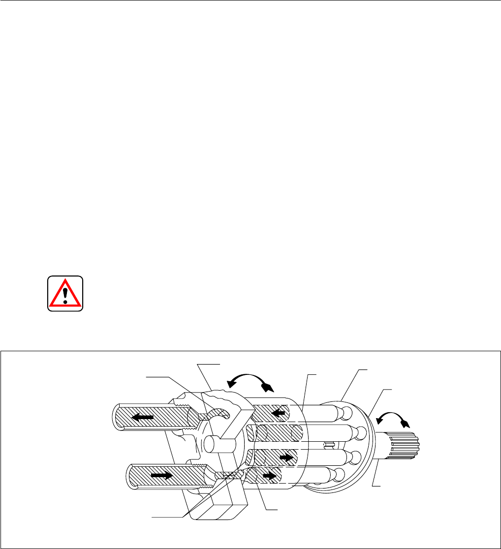
Figure 2.
Inlet Port
Drive Shaft
Outlet Wafer Plate
Kidney Slot
Outlet Port
Wafer Plate
Shoe Plate
Yoke Face
Cylinder
Block Bore
Intake Kidney
Slot Area
Piston


