


29
2. Install pipe plug (69) into valve block (26) and secure.
3. Assemble a new O—Ring (68) on hex plug (67) and
thread plug into place.
K. Shaft Bearing Preload Adjustment
(PVE 19/21 only)
NOTE
If the shaft bearings, shaft, valve block or housing
were not replaced, use the bearing spacer removed
during the disassembly procedure to preload the
shaft and perform step K.7. If preload adjustment is
necessary, perform steps K.1 through K.7
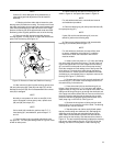
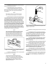
1. Install the thickest bearing spacer (33) over shaft (48)
with the chamfer facing into the housing (toward the
shoulder on the shaft).
2. Slide new bearing (32) on the shaft and up against
spacer (33). The small diameter of the tapered roller bearing
must face out of the housing.
3. Install housing (27) to valve block (26) without gasket
(30) and rotating group. Turn shaft (48) to seat the bearings
then torque the six housing attaching screws (25) to 5 lbf. in.
Check the opening between the valve block and housing to
be as even as possible after tightening.
4. Use a feeler gauge to measure the opening between
valve block (26) and housing (27). Four measurements
should be obtained equidistant around the unit. A tapered
feller gauge is especially useful for this purpose. Average the
four readings by adding them together and dividing by 4.
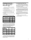
Calculate thickness of the shaft bearing spacer as follows:
0.150
0.027
0.003 ±0.001
0.020
0.146±0.001
Measured thickness of bearing spacer
Average gap (estimated)
Preload setting
Compressed thickness of gasket
Required bearing spacer thickness to
provide a 0.003±.001 bearing preload.
+
–
+
+
5. Remove six mounting screws (25) then remove hous-
ing (27) from the valve block.
6. Remove bearing (32) and bearing spacer (33).
7. Locate a bearing spacer with calculated dimensions
and place next to the new bearing on the shaft. Chamfer must
face shoulder on shaft. Use the original spacer and bearing if
preload is not performed. Set aside for final assembly.
L. Final Assembly of the PVE Series
Pump
NOTE
Lubricate all moving parts of the piston pump with
system fluid to facilitate assembly and provide initial
lubrication. Pour system fluid liberally over the rotat-
ing group and wafer plate as these parts are without
lubrication until the pump primes.
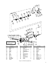
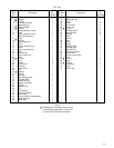
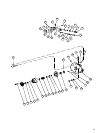
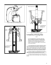
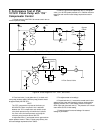
1. Assemble wafer plate locating pin (29) into valve
block (26). Refer to Figure 13.
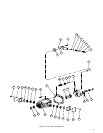
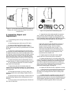
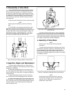
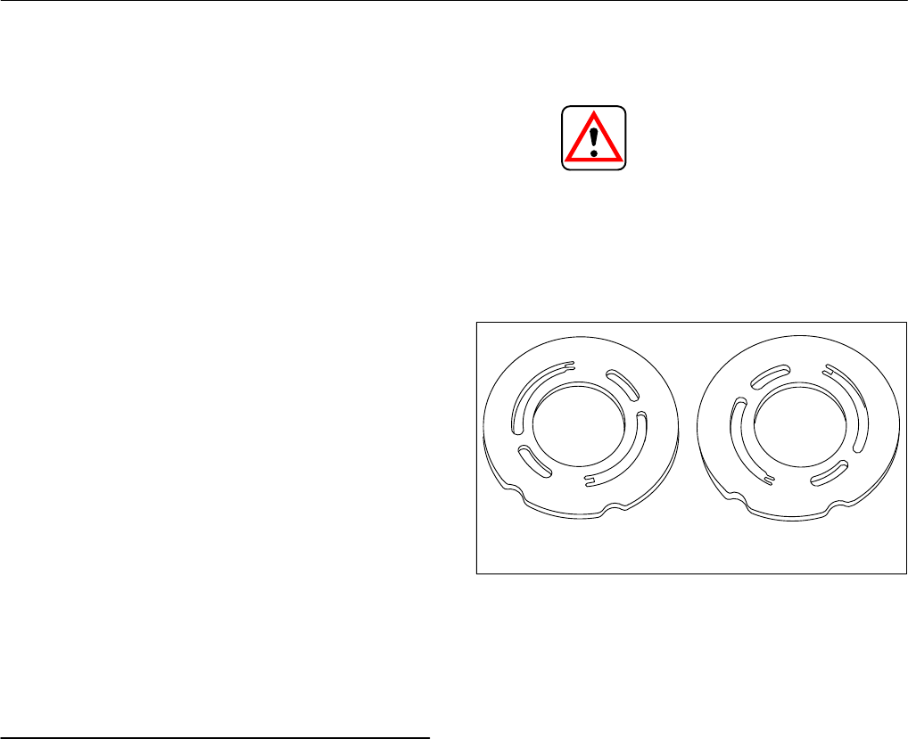
2. Assemble wafer plate (28) over the bearing race (pins
on the PVE12) and locating pin (29) with wear surface away
from valve block (26). Determine from the model code which
wafer plate is used. See Figure 22.
CAUTION
The wafer plate must be flat against the valve block
face. Check to make sure it does not rock back and
forth. If rocking of the wafer plate occurs, check
locating pin (29), it may not be bottomed out in the
valve block. Rocking of the wafer plate will induce
high stress conditions across the wafer plate and
cause fractures to appear.
Figure 22. Wafer plates showing right and left hand.
Left Right
3. Place valve block (26) on its side. See Figure 13 for
position required.
4. Install compensator piston rod (73) into valve block
(26) and attach spirolox retaining ring (71).
5. Install a new O-Ring (70) in the compensator piston
rod O-Ring groove.
6. Install compensator piston (72) over compensator
piston rod (73).
7. Assemble housing (27) and valve block (26) together
as shown in Figure 13. Thread six screws (25) hand tight
through the housing into the valve block. Cross torque the
screws to bring the valve block and housing together against
gasket (30). Final torque screws (25) to 31–35 N.m (23–26
lbf. ft.) for the PVE19/21 and 22-27 N.m. for the PVE12.
8. Check the shaft torque to verify correct bearing pre-
load. If the torque exceeds eight (8) N.m (6 lbf. ft.), perform a
shaft bearing preload adjustment, Section VI.K. and repeat
steps VI.L.7 and 8.
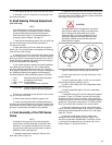
9. Determine shaft rotation from the model code
stamped on the mounting flange. Refer to Figure 7 and
mount the compensator subassembly. Thread four screws
(1) through the compensator into valve block (32). Cross
torque screws to 7–8 N.m (60–70 lbf.in.).