


18
Section VI – Overhaul
A. General
CAUTION
Before breaking a circuit connection, make certain
that power is off and system pressure has been
released. Lower all vertical cylinders, discharge
accumulators, and block any load whose movement
could generate pressure.
After removing the pump from the system and before
disassembly, cap or plug all ports and disconnected
hydraulic lines. Clean the outside of the unit thoroughly
to prevent entry of dirt into the system.
CAUTION
Absolute cleanliness is essential when working on a
hydraulic system. Always work in a clean area. The
presence of dirt and foreign materials in the system
can result in serious damage or inadequate operation.
Periodic maintenance of the pump will generally not require
disassembly to the extent described here. However, the
sequence can also be used as a guide for partial
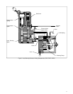
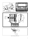
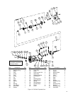
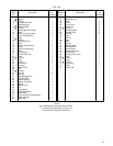
disassembly. In general, disassembly is accomplished in the
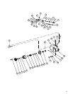
item number sequence shown in Figure 13. Special
procedures are included in the following steps.
NOTE
Discard and replace all O-Rings, gaskets, and shaft
seals removed during disassembly.
B. Disassembly
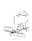
Removal and Disassembly of the Compensator S/A
a. Remove four screws (1) that hold the compensator
S/A to valve block (26) and pull the compensator away from
the valve block.
b. Remove compensator gasket (2) and O-Ring (3)
from body (11) of compensator S/A.
c. Remove lockwire (4), plug (5) and O-Ring (7)
(6 and 7 on the CV compensator).
d. Remove spring (8), seat (9), and spool (10) from
the compensator body (11) and set aside for inspection.
e. Do not remove plug(s) (24) unless it is necessary
for inspection of the bore.
NOTE
The following steps concern only the CVP and
CVPC compensator S/A.
f. Unscrew plug (12) and remove parts (13)
through (18).
g. Remove plug (19) to gain access to orifice plug
(20). Remove orifice plug (20). Do not remove check valve
S/A (21) from body (11). Item (20) may or may not be an ori-
fice. If the circuit has a bleed down, orifice (20) may be a plug.
h. Remove plug (22) and O-Ring (23).
i. Remove plug(s) (24) only if necessary to inspect
the spool bore.
NOTE
All parts must be thoroughly cleaned and kept clean
during inspection and assembly. The close tolerance of
the parts makes this requirement very important. Clean
all removed parts using a commercial solvent that is
compatible with the system fluid. Compressed air may
be used in cleaning, but it must be filtered to remove
water and contamination. Clean compressed air is
particularly useful in cleaning the spool, compensator
body, and valve block passages.
C. Inspection Repair and Replacement
NOTE
Replace all parts that do not meet the following
specifications.
1. Inspect all components for excessive wear, erosion,
and/or seizure.
2. Inspect plugs (5), (12), (19), (20), (22) and (24) for
damaged threads, burrs, etc. Make sure orifice hole is open
in plug (20). Replace if defective.