


www.desatech.com
111245-01B
16
INSTALLATION
Continued
WARNING: Failure to connect
all wires properly as indicated
may cause electrical short circuit
or personal injury. A qualified
electrician should check that all
connections are made properly.
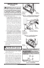
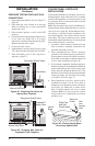
12. Plug in blower power cord.
a. If your firebox is installed as a free-
standing unit with an accessory mantel,
determine whether the power cord will
exit the left side or the right side of the
firebox. Install one plastic bushing provided
into the 1
1
/
2
" hole in the floor support on
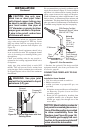
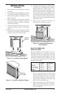
the exit side. Install the second bushing
provided into the 1
1
/
2
" hole in the outer
casing through which the power cord will
exit (see Figures 21 and 22). Route power
cord through plastic bushings and plug the
power cord into a properly grounded three-
prong wall receptacle near the firebox.
b. If your fireplace system installation is
recessed and if an outlet is not installed in
your fireplace, you must install the GA3555
Outlet kit with cover in your fireplace which
will supply a convenient 3-prong grounded
electrical outlet for your blower. Refer to the
installation manual provided with the model
GA3555 accessory for instructions on wiring
the duplex outlet. Note: A qualified installer
must make all electrical connections.
13. Check to make sure that the power cord and all
wires are completely clear of the blower wheel
and that there are no other foreign objects in
blower wheel.
CAUTION: Never touch the
blower wheel while in operation.
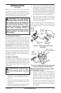
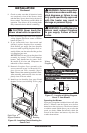
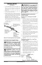
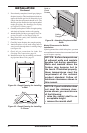
14. Peel off backing paper and stick supplied
wiring diagram decal near center of firebox
bottom (see Figure 23).
15. If gas connections have been made and
checked, replace fireplace floor assembly in
fireplace. Feed flexible gas supply line into
fireplace base area while replacing fireplace
floor assembly. Make sure the entire flexible gas
line is in fireplace base area. IMPORTANT: Do
not pick up fireplace floor assembly by burners.
This could damage burners. Only handle base
by grates. Note: Be careful of all wires and
components on underside of floor assembly.
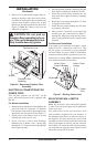
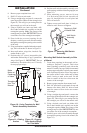
Figure 21 - Installing Plastic Bushing for
Power Cord (Right Side Exit Shown)
Right Floor
Support
Bracket
Plastic
Bushing
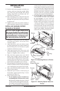
Figure 22 - Installing Bushings
(Left Side Exit shown)
Bushing Location for
Recessed Installation
Bushing
Location for
Freestanding
Installation
Plastic
Bushing
V
a
r
i
a
b
l
e
F
a
n
S
w
i
t
c
h
W
h
it
e
W
h
it
e
B
l
a
c
k
G
r
e
e
n
O
n
1
1
0
/
1
1
5
V
.A
.
C
.
Blow
e
r
Moto
r
B
l
a
c
k
B
l
a
c
k
B
l
a
c
k
O
f
f
Figure 23 - Location of Wiring Diagram
Decal 3" from Blower
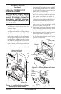
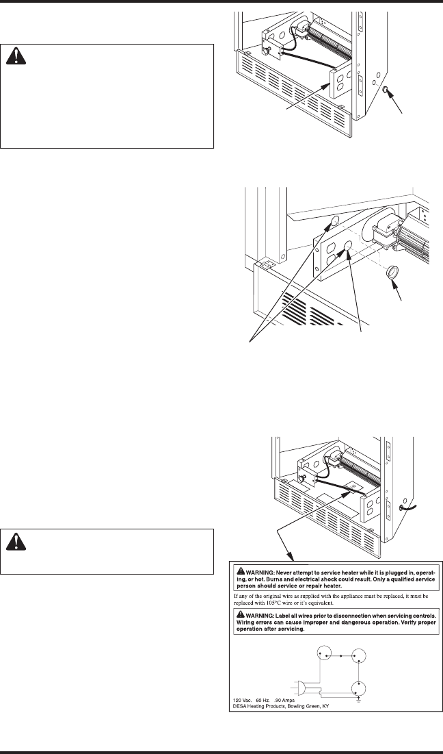
Wiring
Diagram
Red
Va
riable
Fan Switch
Fan Switch
(N.O.)
Green
White
On
11
0/115
V.
A.C.
Blower
Motor
Black
Off
1
2
Black
Blue