


www.desatech.com
111245-01B
22
3. If not already completed, install gas piping to
fireplace location. This installation includes an
approved flexible gas line (if allowed by local
codes) after the equipment shutoff valve. The
flexible gas line must be the last item installed
on the gas piping. See Installing Gas Piping
to Fireplace Location
, page 17.
4. Carefully set fireplace in front of rough opening
with back of fireplace inside wall opening.
5. Attach flexible gas line to gas supply. See Con
-
necting Fireplace to Gas Supply, page 18.
6. Plug electrical cord(s) into electrical outlet
installed in step 2.
7. Carefully insert fireplace into rough opening.
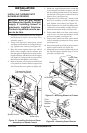
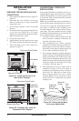
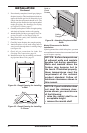
8. Attach fireplace to wall studs using nails or
wood screws through holes in nailing flange
(see Figure 36).
9. Check all gas connections for leaks. See
Checking Gas Connections, page 19.
10. Install brass trim. See Assembling and Attach
-
ing Optional Brass Trim
, page 23
INSTALLATION
Continued
35
1
/2"
17
3
/4"
33"
39
3
/8"
27
7
/
8
"
55
5
/8"
35
1
/2"
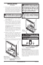
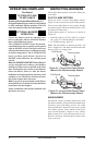
Figure 34 - Rough Opening for Installing
in Wall
Figure 35 - Rough Opening for Installing
in Corner
Figure 36 - Attaching Fireplace to Wall
Studs
Nailing
Flanges
Nails or
Wood
Screws
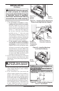
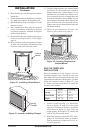
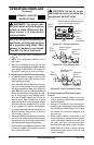
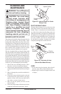
Mantel Clearances for Built-In
Installation
If placing mantel above built-in fireplace, you must
meet minimum clearance between mantel shelf and
top of fireplace opening.
NOTICE: Surface temperatures
of adjacent walls and mantels
become hot during operation.
Walls and mantels above the
firebox may become hot to
the touch. If installed properly,
these temperatures meet the
requirement of the national
product standard. Follow all
minimum clearances shown in
this manual.
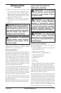
NOTICE: If your installation does
not meet the minimum clear-
ances shown, you must do one
of the following:
• raise the mantel shelf to an
acceptable height
• remove the mantel shelf