


www.desatech.com
111245-01B 13
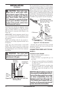
13. Position wall switch assembly vertically over
opening with decal lettering upright. Make
sure wires freely pass through wall without
binding. Align holes in wall plate with 1/8"
pilot holes in mantel wall.
14. Drive mounting screws, removed in step 2 of
Relocating Wall Switch Assembly on page 10,
through wall plate holes and into pilot holes
in mantel wall.
15. Tighten screws until wall switch assembly is
firmly attached to mantel. Do not overtighten.
INSTALLING VARIABLE SPEED
BLOWER ACCESSORY
NOTICE: Shut off gas supply and
disconnect heater from gas supply
if installing blower into previously
installed fireplace. Contact a quali
-
fied service person to do this.
1. If fireplace screen and floor are still installed,
see Removing Fireplace Screen and Floor
Assembly, page 9.
2. Attach the power cord to the blower motor
by firmly pushing the two female terminals at
the end of the power cord onto the two spade
terminals on the blower motor.
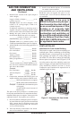
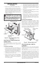
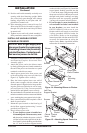
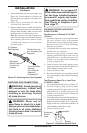
3. Attach green ground wire from power cord
to blower housing using screw provided (see
Figure 14). Tighten screws securely.
4. Place the blower against lower rear wall of
firebox outer wrapper with the exhaust port
directed upward. Align the holes in top mount
-
ing tabs of blower with holes in wall of wrap
-
per (see Figure 14). Using 2 screws provided,
mount blower and tighten screws securely.
5. Be certain that all wire terminals are securely at
-
tached to terminals on blower motor and that the
screw retaining the green ground wire is tight.
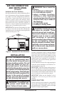
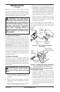
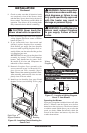
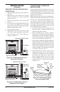
6. Place control knob provided on plastic control
shaft of speed control.
7. Mount the speed control on the front leg of
the left floor support bracket using 2 screws
provided (see Figure 15).
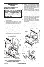
8. Plug in blower power cord.
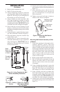
a. If your fireplace system is installed as a
freestanding unit with an accessory man
-
tel, determine whether the power cord will
exit the left side or the right side of the fire
-
box. Install 1 plastic bushing provided into
the 1.5" hole in the floor support bracket
INSTALLATION
Continued
Figure 14 - Mounting Blower to Firebox
Lower Rear
Wall of Firebox
Blower
Top
Mounting
Tab
Exhaust
Port
Screw
Green Ground Wire
Screws
Figure 15 - Attaching Speed Control to
Firebox
Screws
Speed
Control
Control
Knob
Left Floor
Support Bracket
Control
Shaft
on the exit side (see Figure 16). Install the
second plastic bushing provided into the
1.5" hole in the outer casing through which
the power cord will exit. Route power cord
through both plastic bushings and plug
the power cord into a properly grounded
3-prong wall receptacle near the firebox.
b. If your fireplace system installation is
recessed and if an outlet is not installed
in your fireplace, you must install the
GA3555 Outlet kit with cover in your
fireplace which will supply a convenient
3-prong grounded electrical outlet for
your blower. Refer to the installation
manual provided with the model GA3555
accessory for instructions on wiring the
duplex outlet.
Note: A qualified installer
must make all electrical connections.