


www.desatech.com
111245-01B 15
INSTALLING THERMOSTATIC
BLOWER ACCESSORY
NOTICE: Shut off gas supply
and disconnect heater from gas
supply if installing blower in
previously installed fireplace.
Contact a qualified service per
-
son to do this.
1. If fireplace screen and floor are still installed,
see Removing Fireplace Screen and Floor
Assembly, page 9.
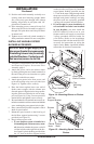
2. Using screw provided, attach green ground
wire from speed control cord to blower hous
-
ing. Tighten screw securely (see Figure 18).
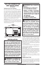
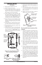
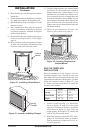
3. Place the blower against lower rear wall of
firebox outer wrapper with the exhaust port
directed upward. Align the holes in top mount
-
ing tabs of blower with holes in wall of wrapper
(see Figure 19). Using two #8 screws provided,
mount blower and tighten screws firmly.
4. Remove the three screws (do not discard) and
cover plate from center of firebox wrapper rear
wall. Discard this cover plate (see Figure 18).
INSTALLATION
Continued
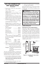
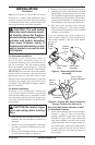
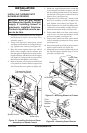
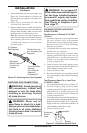
Figure 18 - Installing Switch and Cover
Assembly and Speed Control
Thermostatic Switch
and Cover Assembly
Red
Wire
Blue Wire
Black
Wire
Green Wire
Speed Control
White
Wire
5. Mount the supplied thermostatic switch and
cover assembly into firebox wrapper wall. Do
this by feeding terminal ends of wire harness
into the hole. Allow wires to fall to bottom of
firebox cavity (see Figure 18).
6. Using three screws from step 7, attach switch
and cover assembly to firebox wrapper rear
wall. Tighten screws firmly (see Figure 18).
7. Firmly attach red wire from the thermostatic
switch and cover assembly to either of the ter
-
minals on the blower motor (see Figure 18).
8. Firmly attach black wire from speed control
cord to blue wire from thermostatic switch
and cover assembly (see Figure 18).
9. Firmly attach white wire from speed control
cord to remaining terminal on blower motor
(see Figure 18).
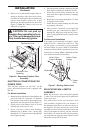
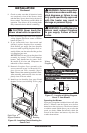
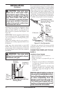
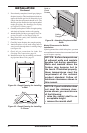
10. Place control knob provided on plastic control
shaft of speed control (see Figure 20).
11. Mount the speed control onto the front leg of
the left floor support bracket using 2 screws
provided (see Figure 20).
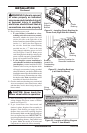
Blower
#8 Screws
Figure 19 - Mounting Blower to Firebox
Lower Rear
Wall of
Firebox
Exhaust
Port
Top
Mounting
Tab
Control
Knob
Screws
Speed
Control
Floor
Support
Bracket
Figure 20 - Attaching Speed Control