


www.desatech.com
111245-01B
10
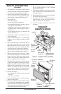
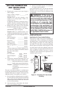
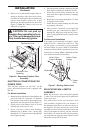
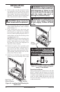
3. Remove screws that attach fireplace floor as-
sembly to fireplace. Open lower louver door.
Carefully lift up fireplace floor assembly and
remove from fireplace, taking care to pull
flexible gas line through the access holes (see
Figure 6). Note: Be careful of all wires on
underside of log base.
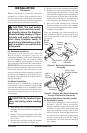
CAUTION: Do not pick up
fireplace floor assembly by burn-
ers. This could damage burners.
Only handle base by grates.
INSTALLATION
Continued
Figure 6 - Removing Fireplace Floor
Assembly
Screws
Fireplace Floor
Assembly
Flexible Gas Line
ELECTRICAL CONNECTIONS FOR
POWER CORD
This fireplace operates on 120 VAC, 60 Hz
power. An electrical power cord is supplied with
this unit.
For Mantel Installation
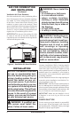
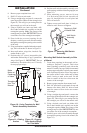
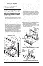
1. Determine from which side of the fireplace the
power cord will exit. Locate the 1.5" diameter
hole near the center of floor support bracket on
appropriate side of lower cavity (see Figure 7).
2. Locate power cord. Remove wire tie or tape
holding plug end of power cord.
3. Power cord has 2 plastic hole bushings
threaded onto it. Route cordʼs 3-prong plug
through the 1.5" diameter hole in appropriate
floor support bracket.
4. Push first plastic bushing completely through
hole. Squeeze bushing as needed to do this.
5. Install the second plastic bushing into the
hole in the floor support bracket by snapping
into place.
6. Route the 3-prong plug through the 1.5" hole
in fireplace outer casing.
7. Install the first plastic bushing into this hole
by snapping into place.
8. After you have connected to gas supply and
checked your gas connections (see pages 17
through 20), plug power cord into any conve
-
nient 3-prong grounded wall receptacle near
fireplace.
For Recessed Installation
If an outlet is not installed in fireplace, install
model GA3555 - Outlet Kit with Cover. This
kit will supply a convenient 3-prong grounded
electrical outlet for power. Refer to installation
manual provided with this optional accessory for
instructions on wiring.
Note: A qualified installer
must make all electrical connections.
RELOCATING WALL SWITCH
ASSEMBLY
Note: The decorative wall switch plate supplied
is white. The wall switch plate may be painted to
match your decor.
The push-button switch and decorative wall
plate assembly supplied with your fireplace is
pre-mounted at the factory in the lower cavity of
the fireplace. You may relocate this wall switch
assembly to a more convenient location such as the
side of your mantel or directly onto the wall near
the fireplace. To mount the wall switch assembly,
you must first cut openings in the mantel or wall
where the switch will be located.
Figure 7 - Routing Power Cord
Power
Cord
Bushings
Hole in Floor
Support Bracket
Hole in Outer
Casing