


www.desatech.com
118531-01A 21
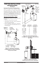
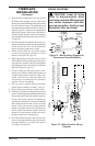
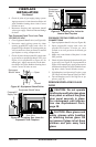
Blue
Variable
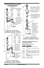
Fan Switch
Fan Switch
(N.O.)
Green
White
On
110/115
V.A.C.
Blower
Motor
Black
Off
1
2
Black
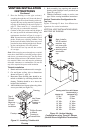
FIREPLACE
INSTALLATION
Continued
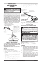
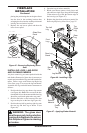
3.
Place the blower against the lower rear wall of
the rebox outer wrapper with the exhaust port
directed upward and the thermodisc positioned up
near the replace bottom. The thermodisc must
be oriented near the replace bottom as shown in
Figure 30, page 20, in order to sense temperature
and properly operate. The blower will be held in
position against the back wall by the magnets
incorporated onto the blower housing (see Figure
30, page 20).
4. Be certain that all wire terminals are securely at-
tached to terminals on blower motor and thermal
switch and that the screw for the thermodisc
bracket and green ground wire is tight.
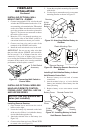
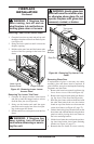
5. Mount speed control box by placing plastic
control shaft through opening in switch
bracket (see Figure 28, page 19).
6. While supporting speed control, secure control
shaft with lock nut by pushing and turning lock
nut with pliers clockwise until it is tight against
mounting plate. Place control knob provided on
shaft (see Figure 28, page 19).
7. Check to make sure that power cord is com-
pletely clear of blower wheel and that there are
no other foreign objects in blower wheel. Also
double check all wire leads and make sure
wire routing is not pinched or in a precarious
position. Correct accordingly.
8. Turn on power to duplex outlet if previously
turned off per warning in column 1, page 19.
9. Plug in blower power cord to duplex outlet.
10. The blower will only run when the speed control
knob is in the ON position and the thermal switch
senses temperature after the replace begins to
heat up. The blower speed can be adjusted by
rotating the control knob. To turn off, turn knob
fully counterclockwise until it clicks off. If the
blower is ON and has been running with the
replace operating, the blower will continue to
run for a short time after the replace has been
turned off. As the thermal switch cools down,
the blower shuts down automatically.
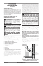
11. Peel off the backing paper and stick the sup-
plied wiring diagram decal on the rebox bot-
tom approximately 12" in front of the blower
(see Figure 29, page 20).
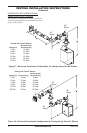
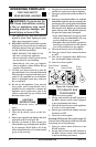
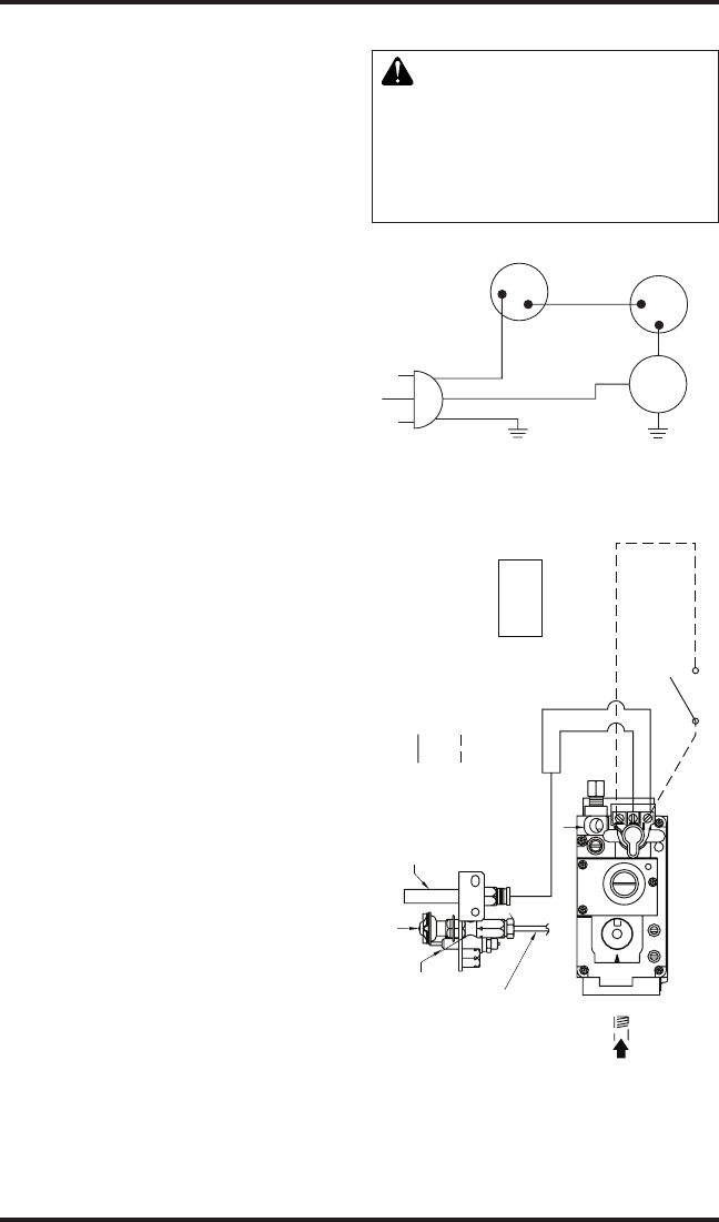
WIRING DIAGRAMS
-
Figure 31 - Blower Wiring Diagram for
Thermostat-Controlled Models
DO NOT
CONNECT
RED
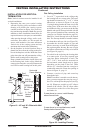
REPLACE FACTORY WIRING WITH 105°C
EQUIVALENT OR HIGHER RATING
THERMOSTAT WIRE 18 GA. RED/WHITE
EXTERNAL WIRING USE ONLY CLASS 2
WHITE
TH/TP
TP
TH
WALL SWITCH
TO 120V
THERMOPILE
PILOT
BURNER
IGNITOR
LINE
PILOT GAS
O
F
F
P
I
L
O
T
O
N
PILOT SAFETY VALVE
MAIN GAS
INCOMING
SUPPLY
Figure 32 - Millivolt Ignition Wiring
Diagram