


www.desatech.com
118531-01A26
FIREPLACE
INSTALLATION
Continued
-
-
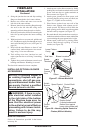
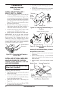
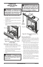
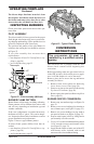
1. Grasp the lower louver panel and pull up until
the hanger brackets release from the door pins
(see Figure 43).
2. Swing the louver panel out until it clears the
replace opening.
3. Pull the entire panel out until the bottom tabs
are free of the slot openings in the lower face
frame.
Figure 43 - Removing Lower Louver
Access Panel
Door Pin
Hanger Bracket
Lower Louver
Access Panel
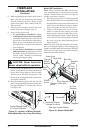
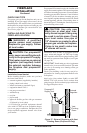
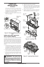
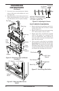
1. Grasp the two hanger brackets at the bottom
and pull up until the hanger brackets release
from the door pins (see Figure 44).
2. Swing out the bracket ends until the upper
panel tabs can be angled out of the slot open-
ings in the upper face frame.
3. Pull the entire louver trim panel out of the face
frame.
-
Figure 44 - Removing Top Louver Trim
Panel
Panel Tabs
Top Louver
Trim Panel
Door Pin
Hanger
Bracket
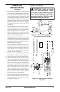
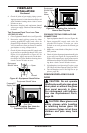
If replacement of glass is necessary, the entire
assembly, glass and frame, must be replaced. If
glass is broken, wear gloves and tape the remaining
fragments onto the frame.
1. Remove the lower louver panel (see Removing
Lower Louver Access Panel and Figure 43).
2. Remove the top louver trim panel (see Remov-
ing Top Louver Trim Panel and Figure 44).
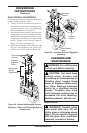
3. Hold the glass frame with one hand and with
the other hand unlock the two door latches
found on top of the rebox to release tension
on the door frame (see Figure 45, page 27).
4. Unhook the locking clasp from the tabs on the
door frame and with both hands swing the door
panel out while pivoting the lower frame on
the lower retaining bracket.
5. Lift the lower frame tabs out from the position-
ing slots found on the lower frame retaining
bracket (see Figure 45, page 27).
6. Remount the new frame in reverse order by