


www.desatech.com
118531-01A16
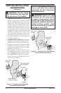
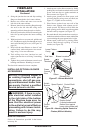
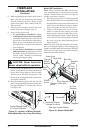
5. Place the ashing over the pipe section(s)
extending through the roof. Secure the base of
the ashing to the roof and framing with roof-
ing nails. Be sure roong material overlaps the
top edge of the ashing as shown in Figure 19,
page 15. There must be a 1" clearance from
the vent pipe to combustible materials.
6.
Continue to add pipe sections until the height of
the vent cap meets the minimum building code
requirements described in Figure 9 on page 9.
Note: You must increase vent height for steep roof
pitches. Nearby trees, adjoining rooines, steep
pitched roofs and other similar factors may cause
poor draft or down-drafting in high winds. Increas-
ing the vent height may solve this problem.
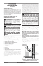
7. Twist-lock the vent cap onto the last section
of vent pipe.
Note: If the vent pipe passes through any occupied
areas above the rst oor, including storage spaces
and closets, you must enclose pipe. You may frame
and sheetrock the enclosure with standard construc-
tion material. Make sure and meet the minimum
allowable clearances to combustibles. Do not ll
any of the required air spaces with insulation.
1. Plumb and locate knockout area for vent pipe.
2. Cut and frame ceiling joist to dimensions
shown in Figure 11, page 11.
3. Determine where restop plate should be at-
tached to thimble by test-tting thimble into
framing. Thimble should be at or above the
height of the insulation.
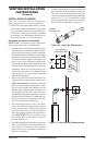
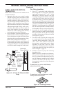
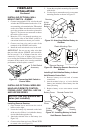
4. Attach thimble into restop plate using 4 hex
screws provided (see Figure 21).
VENTING INSTALLATION
INSTRUCTIONS
Continued
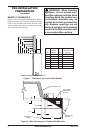
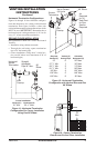
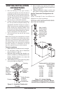
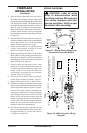
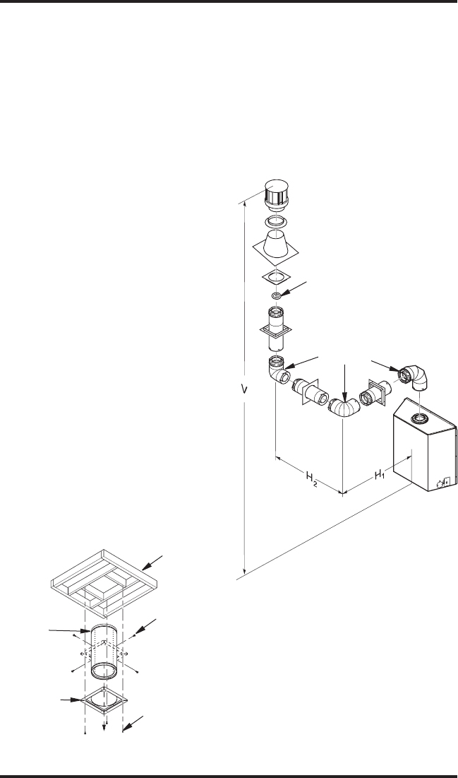
Figure 22 - Vertical Venting
Conguration using Three 90° Elbows
(Vertical Round High Wind Termination)
Horizontal (H
1
Horizontal (H
2
8' Min. 5' Max
10' Min. 8' Max
12' Min. 11' Max
14' Min. 14' Max
16' Min. 17' Max
18' Min. 20' Max
40' Min. 20' Max
90° Elbow
Note: Install a
VR-58 vertical
restrictor ring
into inner pipe
section prior to
attaching vent
termination
cap.
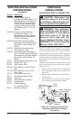
Framing
Top of
Thimble
Should
Measure
to Top of
Insullation
Hex Screw
to Attach
Firestop to
Thimble
Phillips Screws
to Attach
Firestop to
Framed Hole
Firestop
Figure 21 - Installing Thimble with
Firestop
5. Ret assembly into opening and attach to
framing with 8 phillips screws provided (see
Figure 20, page 15).
6. Thimble installation is ready to receive vent
pipe. Follow venting installation instructions.
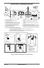
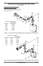
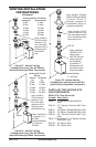
Figures 22 through 25 show four different con-
gurations for vertical termination.
VERTICAL VENT INSTALLATIONS USING
MULTIPLE 90° ELBOWS