


www.desatech.com
118531-01A18
VENTING INSTALLATION
INSTRUCTIONS
Continued
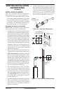
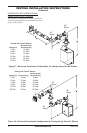
CVVK-58 Ceiling Vertical Vent Kit
(Includes: 30° Offset Return, 7"-12"
Adjustable Pipe, Flue Restrictor,
Vertical High Wind Termination,
3' Pipe, 4' Pipe, Firestop Plate,
Firestop Thimble, Storm Collar,
Roof Flashing [0/12 - 6/12], 38
Screws)
CHVK-58 Corner Horizontal Vent Kit,
(Includes 90° Elbow, 7"-12"
Adjustable Pipe, Wall Firestop,
Horizontal Square Termination,
6" Pipe, 18 Screws)
HHTK-58 High Wind Round Horizontal
Termination Kit (Includes Round
Termination, Wall Firestop, 45°
Elbow)
HHT-58 High Wind Round Horizontal
Termination Kit, Galv.
HTS-58 Horizontal Square Termination,
Galv. HTKS-58 Horizontal Square
Termination Kit (Includes: Square
Termination, Wall Firestop, 45°
Elbow)
VT-58 Vertical Round Termination, Galv.
SC-58 Storm Collar, Galv.
WF-58 Wall Firestop, Galv.
RF-58-6 Roof Flashing - 0 to 6/12 Pitch,
Galv.
RF-58-12 Roof Flashing - 6/12 to 12/12
Pitch, Galv.
VR-58 Vertical Restrictor, Galv.
S-58 Vinyl Siding Standoff, Galv.
WS-58 Wall Strap
CS-58 Cathedral Ceiling Support
FP-58 Firestop Plate
SF-58 Stucco Flashing -
For use with HTS-58
RF-58 Flat Roof Flashing
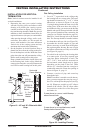
FIREPLACE
INSTALLATION
ELECTRICAL SUPPLY CONNECTION
CAUTION:
Disconnect the
-
WARNING:
-
-
sence of local code, with the
current National Electric Code,
ANSI/NFPA 70, or the Canadian
Electric Code, CSA C22.1
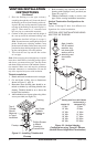
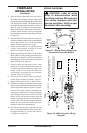
A prewired junction box receptacle with strain
relief is provided on the right side of the cabinet
for hard wiring the unit to a 15 Amp, 120VAC,
60Hz grounded branch circuit. If the installation
demands that the electrical supply be connected
from the left side, the entire receptacle box can
be relocated to the left side by following these
instructions:
Note: If you do not need to relocate the junction
box, to connect the electric supply follow steps 8
through 11 only:
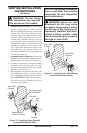
1. Remove 2 screws and outer cover with strain
relief bushing on right side of cabinet (see
Figure 26).
2. Remove inner retaining screw on junction box
mounting tab.
3. Slide junction box up until screw mounting
tab is lined up to notch in outer cabinet.
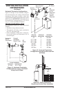
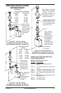
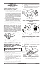
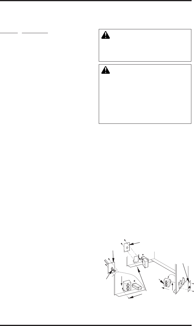
Figure 26 - Relocating Junction Box
Receptacle and Electrical Supply
Connection
J-Box Cover
with Strain
Relief
J-Box
Cover
Romex
Cable
J-Box with
Receptacle
J-Box Cover with
Strain Relief
Screw/Tab
Retainer