


www.desatech.com
118531-01A22
FIREPLACE
INSTALLATION
Continued
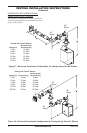
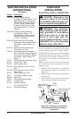
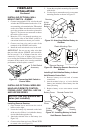
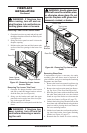
Figure 33 - Connecting Wall Switch to
Control Valve
To Wall Switch
Accessory
INSTALLING OPTIONAL WALL
MOUNT SWITCH - GWMS2
1. Connect one terminal of 25 ft. wire for the wall
switch to the TPTH terminal on the valve. Con-
nect remaining wire terminal to the TH terminal
on the valve. Make sure that the wire terminals
are in the positions on the unit as pictured in
Figure 33. If wires are not connected as shown
the switch will not work.
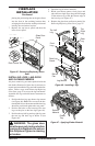
2. Route the 25 ft. wire through openings pro-
vided on the sides of the burner system to a
convenient location to mount your switch.
3. Connect one bare wire end to each of the
terminals of the GWMS2 wall switch.
4. Install the wall switch and cover in the wall.
IMPORTANT: Do not use any other wire than
that provided with the GWMS2 wall switch kit.
Do not exceed 15 ft. of distance from the valve
connection. Using wire of higher gage or turns
or exceeding the minimum distance will increase
resistance at the control valve causing unreliable
performance of the replace controls.
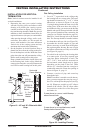
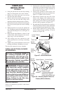
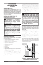
Figure 34 - Attaching Alkaline Battery to
Receiver
9-Volt
Alkaline
Battery
Receiver
Terminal
Wires
Battery Clip
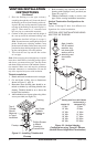
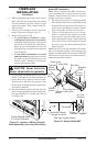
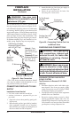
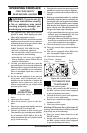
Figure 35 - Mounting Remote Receiver to
Bracket
Held Remote Control Unit
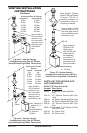
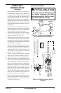
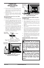
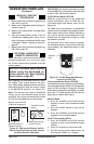
1. Remove battery cover on back of remote
control unit.
2. Attach terminal wires to a 9-volt alkaline
battery (not included). Place battery into the
battery housing.
3. Replace battery cover onto remote control
unit.
Figure 36 - Installing Battery in Hand-
Held Remote Control Unit
9-Volt
Battery
Battery
Housing
Battery Cover
Terminal
Wires
Remote Control Unit
Towards Front
REMOTE ON OFF
Remote Receiver
Plastic Mounting Clips
INSTALLING OPTIONAL WIRELESS
HAND-HELD REMOTE CONTROL
FOR MILLIVOLT IGNITION - HRC100
AND HRC200 SERIES
-
1. Open bottom louver and locate the switch
bracket on the right
2. Locate the battery clip mounted on the back
of the receiver. Slide a 9-volt alkaline battery
(not included) through the clip
3. Attach the terminal wires to the battery (see
Figure 34).
4. Connect wires from receiver to TH and TPTH
to control valve (see Figure 33).
5. Locate the two plastic mounting clips provided
with the kit.
6. Use the clips to mount the receiver on remote
mounting bracket as shown in Figure 35.