


www.desatech.com
118531-01A 31
OPERATING FIREPLACE
Continued
The blower helps distribute heated air from
the replace. Periodically check the louvers of
the rebox and remove any dust, dirt or other
obstructions that will hinder the ow of air.
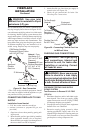
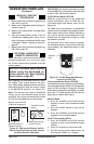
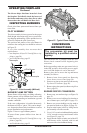
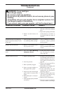
Thermocouple
Thermopile
1/8"
Pilot Burner
Piezo
Ignitor
Figure 52 - Pilot Assembly (Millivolt)
3/8" to 1/2"
INSPECTING BURNERS
Check pilot ame pattern and burner ame pat-
terns often.
The pilot assembly is factory preset for the proper
ame height. Alterations may have occurred dur-
ing shipping and handling. Call a qualied service
person to readjust the pilot if necessary.
The position and pattern of the pilot ames in
relation to the sensing devices should be as shown
in Figure 52.
If you pilot assembly does not meet these
requirements:
• turn replace off (see To Turn Off Gas to Ap-
pliance, page 28)
• see Troubleshooting, page 35
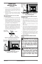
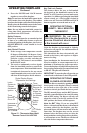
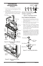
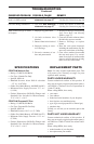
Figure 53 - Typical Flame Pattern
Burner ames will be steady; not lifting or oating.
Flame patterns will be different from unit to unit
and will vary depending on installation type and
weather conditions.
If the vent conguration is installed incorrectly,
the ames will lift or "ghost". This can be danger-
ous. Inspect the ames after installation to ensure
proper installation and performance.
Figure 53 shows a typical ame pattern.
If burner flame pattern differs from that de-
scribed:
• turn replace off (see To Turn Off Gas to Ap-
pliance, page 28)
• see Troubleshooting, page 35
CONVERSION
INSTRUCTIONS
The conversion kit is packaged with the unit.
Please check contents before beginning this
conversion.
Before proceeding, make sure gas control valve is
in the OFF position, all electrical power to appli-
ance is off and replace is cool to the touch.
Remove glass door to access the log and burner
assembly as follows:
1. Remove lower louver panel (see Removing
Lower Louver Access Panel, page 26).
2. Remove top louver trim panel (see Removing
Top Louver Trim Panel, page 26).
3. Remove glass door panel (see Removing Glass
Door, page 25).
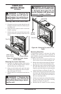
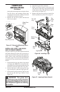
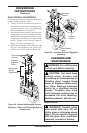
1. Remove top, rear and base logs, see Figure 54,
page 32.
2. Remove two screws holding pilot bracket to
rear of burner pan. (see Figure 54, page 32).
3. Remove two screws holding rear log stand to
rear panel of rebox (see Figure 54, page 32).
4. Expose main burner orice by lifting burner
pan assembly off orice mount.
5. Use a 1 1/8" wrench on bulkhead tting and an
11/16" wrench to remove main burner orice
(see Figure 55, page 32).
6. Apply thread sealant to make end of the #55
main burner orice included with kit and
remount orice into bulkhead tting.