


41
11) Clean the bottom surfaces of the heat exchanger.
12) Put a light in the combustion chamber and look through the flue passages from the top to verify that they have been
thoroughly cleaned.
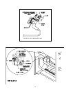
13) Apply a heavy (1/4”) bead of RTV-732 silicone sealant with a 500F intermittent duty temperature rating around the
perimeter of the heat exchanger.
14) Set the flue collector onto the block and press down so that the flue collector is set into the silicone applied in the previous
step.
15) Replace the ¼-20 nuts and washers that hold down the flue collector.
16) Apply a bead of silicone around the outside of the joint between the heat exchanger and the flue collector.
17) Reattach all the jacket components except for the fan cover plate.
18) Install the fan cover plate.
19) Plug in the fan and reconnect the vacuum switch tube.
20) Reconnect the vent system.
WARNING
SOOT DEPOSITS IN THE FLUE PASSAGES ARE A SIGN THAT THE BOILER MAY BE OPERATING AT HIGH
CARBON MONOXIDE LEVELS. AFTER CLEANING THE BOILER OF SOOT DEPOSITS, CHECK BOTH CO AND
CO2 LEVELS IN THE VENT BEFORE LEAVING THE BOILER IN OPERATION. CO AND CO2 READINGS SHOULD
BE BELOW THE MAXIMUM LIMITS SHOWN IN TABLE 8.
Service Notes
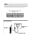
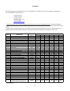
1) Measuring CO and CO2 – If it is necessary to check CO or CO2, the best place to take a gas sample will usually be at the
vent terminal. Table 8 shows typical and maximum readings for CO and CO2 on both natural and LP gas. Do not leave
the boiler in operation if either the CO or CO2 exceeds the maximum limit in this table. Some causes of excessive CO or
CO2 include:
• Incorrectly sized or drilled burner orifice
• Partially plugged flue passages
• Improper manifold pressure
• Partial blockage of vent system
• Foreign material in burner venturis or burner ports
• Distorted burner ports
• Distorted burner venturi bracket
• Damaged fan impeller or housing
• Damaged or missing fan gasket
• Leak in seal between flue collector and heat exchanger
• Inadequate supply of combustion air
• Damaged base
2) Orifice Size
– Refer to the parts list in the back of this manual for sea level orifice sizes. Consult your Crown
representative for correct orifice sizes for use at altitudes above 2000 ft. Orifice for this boiler cannot be drilled in the
field.
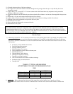
NATURAL GAS LP GAS
TYPICAL CO2 (%) 7.5 8.5
MAXIMUM CO2 (%) 9.0 10.5
TYPICAL CO (PPM) 20 20
MAX. CO (PPM) 70 70
TABLE 8: TYPICAL AND MAXIMUM
A
CCEPTABLE CO2 AND CO READINGS IN FLUE
GAS