


26
VIII System Piping
CAUTION
• INSTALL BOILER SO THAT THE GAS IGNITION SYSTEM COMPONENTS ARE PROTECTED FROM WATER
(DRIPPING, SPRAYING, RAIN, ETC) DURING APPLIANCE OPERATION AND SERVICE (CIRCULATOR
REPLACEMENT, ETC).
• OPERATION OF THIS BOILER WITH CONTINUOUS RETURN TEMPERATURES BELOW 120F CAN CAUSE
SEVERE HEAT EXCHANGER CORROSION DAMAGE.
• OPERATION OF THIS BOILER IN A SYSTEM HAVING SIGNIFICANT AMOUNTS OF DISSOLVED OXYGEN
CAN CAUSE SEVERE HEAT EXCHANGER CORROSION DAMAGE.
• DO NOT USE TOXIC ADDITIVES, SUCH AS AUTOMOTIVE ANTIFREEZE, IN A HYDRONIC SYSTEM.
Standard Piping
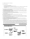
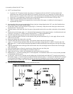
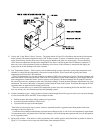
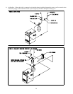
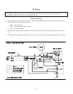
Figure 27 shows typical boiler system connections on a single zone system. Additional information on hydronic system
design may be found in Installation of Residential Hydronic Systems (Pub. #200) published by the Hydronics Institute in
Berkely Heights, NJ. The components in this system and their purposes are as follows:
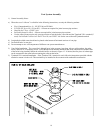
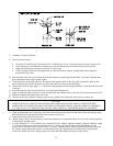
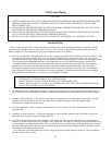
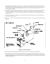
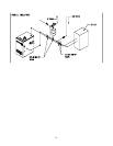
1) Relief valve (Required) – Mount the relief valve in the ¾ tapping on the right side of the boiler as shown in Figure 1 using
the ¾ nipples and elbow provided. The relief valve shipped with the boiler is set to open at 30 psi. This valve may be
replaced with one having a setting of up to the “Maximum Allowable Working Pressure” shown on the rating plate. If the
valve is replaced, the replacement must have a relief capacity in excess of the DOE heating capacity for the boiler.
Pipe the discharge of the relief valve to a location where water or steam will not create a hazard or cause property
damage if the valve opens. The end of the discharge pipe must terminate in an unthreaded pipe. If the relief valve
discharge is not piped to a drain, it must terminate at least 6 inches above the floor. Do not run relief valve discharge
piping through an area that could be subjected to freezing temperatures. The termination of the relief valve discharge
piping must be in an area where it is not likely to become plugged by debris.
DANGER
• PIPE RELIEF VALVE DISCHARGE TO A SAFE LOCATION.
• DO NOT INSTALL A VALVE IN THE RELIEF VALVE DISCHARGE LINE.
• DO NOT INSTALL RELIEF VALVE IN ANY OTHER LOCATION THAN THAT SHOWN IN FIGURE 1.
• DO NOT PLUG RELIEF VALVE DISCHARGE.
2) Circulator (Required) – Although the circulator is shipped on the boiler return, it can be installed on the boiler supply. If
the circulator is moved to the supply, it should be positioned just downstream of the expansion tank as shown in Figure
27.
3) Expansion Tank (Required) – If this boiler is replacing an existing boiler with no other changes in the system, the old
expansion tank can generally be reused. If the expansion tank must be replaced, consult the expansion tank
manufacturer’s literature for proper sizing.
4) Fill Valve (Required) – Either a manual or automatic fill valve may be used. The ideal location for the fill is at the
expansion tank.
5) Automatic Air Vent (Required) – At least one automatic air vent is required. Manual vents will usually be required in
other parts of the system to remove air during initial fill.
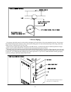
6) Low Water Cut-Off (Required in some situations) – A low water cut-off is required when the boiler is installed above
radiation. In addition, some codes such as ASME CSD-1 require low water cut-offs. Codes may also require that this low
water cut-off have a manual reset function. The low water cut-off may be a float type or probe type but must be designed
for use in a hot-water system. The low water cut-off should be piped into the boiler supply just above the boiler with no
intervening valve between it and the boiler.
Use a low water cut-off that breaks the 120 VAC supply to the boiler. Do not attempt to wire a 24- volt low water cut-
off into the boiler factory wiring.