


3
III Before Installing
1) Safe, reliable operation of this boiler depends upon installation by a professional heating contractor in strict accordance
with this manual and the authority having jurisdiction.
• In the absence of an authority having jurisdiction, installation must be in accordance with this manual and the
National Fuel Gas Code, ANSI Z223.1
• In Canada, installation must be in accordance with CSA B149 (Installation Code for Gas Burning Appliances and
Equipment).
• Where required by the authority having jurisdiction, this installation must conform to the Standard for Controls and
Safety Devices for Automatically Fired Boilers (ANSI/ASME CSD-1)
2) Read Section VI to verify that the boiler can be vented in accordance with these instructions.
3) Make sure that the boiler is correctly sized:
• For heating systems employing convection radiation (baseboard or radiators) use an industry accepted sizing method
such as the I=B=R Heat Loss Calculation Guide (Pub. #H21 or #H22) published by the Hydronics Institute in
Berkeley Heights, NJ.
• For new radiant heating systems refer to the radiant tubing manufacturer’s boiler sizing guidelines.
• For systems including a Crown Mega-Stor indirect water heater, size the boiler to have either the DOE Heating
Capacity required for the Mega-Stor or the net rating required for the heating system, whichever results in the larger
boiler.
• For systems that incorporate other indirect water heaters, refer to the indirect water heater manufacturer’s instructions
for boiler output requirements.
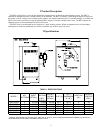
4) Make sure that the boiler received is configured for the correct gas (natural or LP).
5) For installations at altitudes above 2000ft, special orifice and pressure switches may be required. Make sure that the boiler
is configured for use at the correct altitude.
IV Locating the Boiler
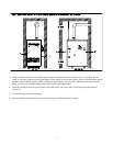
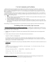
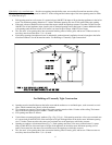
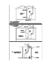
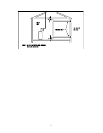
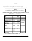
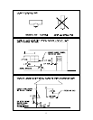
1) Clearances:
• Observe the minimum clearances shown below. These clearances apply to all combustible construction, as well as non-
combustible walls and doors. Also see Figure 2.
Front – 6”
Left Side – 1”
Right Side – 4”
Rear – 1”
Top – 36”
Vent Pipe – 5”
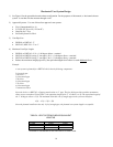
• A 24” service clearance from the jacket is recommended on the left, right, and front of the boiler. These clearances may
be reduced to those shown in Figure 2, however servicing the boiler will become increasingly difficult as these service
clearances are reduced.
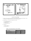
• If the right side 24” service clearance is reduced, adequate clearance must be maintained to easily read both the gauge and
the limit control. Alternatively, access to the gauge and limit may be provided using a door.
2) The boiler must be installed on a hard level surface. This surface may be combustible.