38
c) If the line pressure falls outside of these limits, find and correct the cause of the problem before proceeding further.
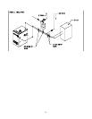
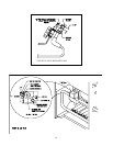
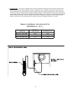
d) Connect a manometer to the manifold pressure tap on the gas valve (Fig. 41a).
e) Read the manifold pressure. It should be set at:
Natural Gas LP Gas
Manifold Press. (inches w.c.) 3.5 10.0
f) If a manifold pressure adjustment is needed, make the adjustment by turning the regulator screw clockwise to raise the
pressure and counter clockwise to reduce the pressure (Fig 39).
g) If a manifold pressure adjustment is made, repeat steps (a)-(c) to be certain that the line pressure is still within acceptable
limits.
h) Replace the cover screw on the regulator.
8) Perform a test of the flame supervision system. While the boiler is firing, disconnect the red ignition cable from the
“Spark” terminal on the ignition module. Both the main and pilot flames should extinguish immediately.
9) Allow the boiler temperature to increase to the high limit setting. Confirm that the high limit shuts down the burners and
the combustion fan.
10) Pinch or disconnect the vacuum switch tube that is connected to the fan. The burner should go out after a few seconds.
11) Confirm that the thermostat(s) cycle the burner and appropriate circulators
12) After the boiler has operated for approximately 30 minutes, check the boiler and heating system piping for leaks. Repair
any leaks found at once.
13) Inspect the vent system for flue gas leaks. Repair any leaks found before leaving the boiler in operation.
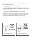
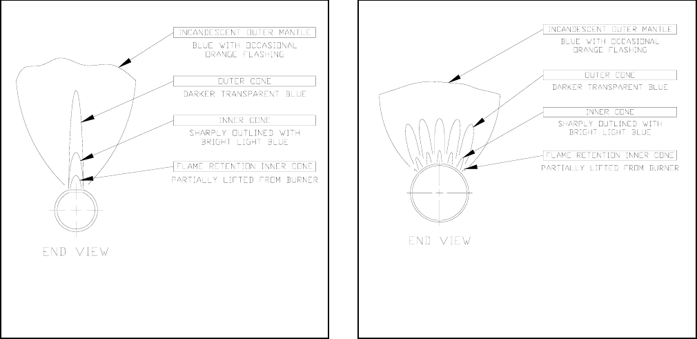
FIGURE 37a: MAIN BURNER FLAME
(1” BURNERS)
FIGURE 37b: MAIN BURNER FLAME
(50mm BURNERS)


