


28
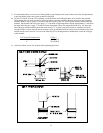
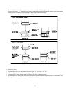
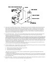
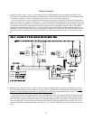
2) Gravity and “Large Water Volume” Systems – The piping shown in Figure 29 will minimize the amount of time that the
boiler operates with return temperatures below 120F on these systems. A bypass is installed as shown to divert some
supply water directly into the return water. The bypass pipe should be the same size as the supply. The two throttling
valves shown are adjusted so that the return temperature rises above 120F during the first few minutes of operation. A
three-way valve can be substituted for the two throttling valves shown. If the circulator is mounted on the supply, the
bypass must be on the discharge side of the circulator.
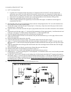
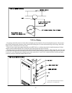
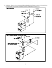
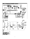
3) Low Temperature Systems – Some systems, such as radiant tubing systems, require the system water temperature to be
limited to a value below the temperature of the water leaving the boiler. These systems also typically have return
temperatures well below the 120F minimum.
Figure 30 illustrates the use of a heat exchanger to connect a BWF boiler to this type of system. The heat exchanger will
permit the transfer of heat from the boiler water to the low temperature system while holding the system supply and boiler
return temperatures within their limits. For this system to work properly, the heat exchanger must be properly sized and
the correct flow rates are required on either side of the heat exchanger. Consult the heat exchanger manufacturer for sizing
information. The water in the boiler is completely isolated from the water in the system. This means that separate fill and
expansion tanks are required for the heating system loop.
There are several other ways to connect low temperature systems to the non-condensing boilers like the BWF such as
four way mixing valve and variable speed injection pumping systems.
4) Systems containing oxygen – Many hydronic systems contain enough dissolved oxygen to cause severe corrosion damage
to a cast iron boiler such as the BWF. Some examples include:
• Radiant systems that employ tubing without an oxygen barrier.
• Systems with routine additions of fresh water.
• Systems which are open to the atmosphere.
If the boiler is to be used in such a system, it must be separated from the oxygenated water being heated with a heat
exchanger as shown in Figure 30.
Consult the heat exchanger manufacturer for proper heat exchanger sizing as well as flow and temperature requirements.
All components on the oxygenated side of the heat exchanger, such as the pump and expansion tank, must be designed for
use in oxygenated water.
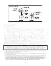
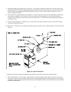
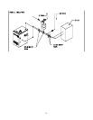
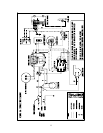
5) Piping with a Chiller – If the boiler is used in conjunction with a chiller, pipe the boiler and chiller in parallel as shown in
Figure 31. Use isolation valves to prevent chilled water from entering the boiler.