


10
Horizontal Vent System Design
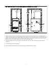
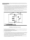
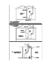
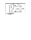
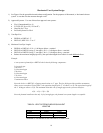
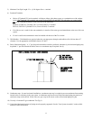
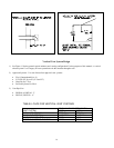
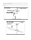
1) See Figure 8 for the general horizontal exhaust configuration. For the purposes of this manual, a “horizontal exhaust
system” is one that exits the structure through a wall.
2) Approved Systems – Use one of these four approved vent systems:
• Flex-L-International Star-34
• Z-FLEX SVE Series III (“Z-Vent II”)
• Heat Fab Saf-T Vent
• ProTech Systems FasNSeal
3) Vent Pipe Size:
• BWF061 to BWF162– 3”
• BWF-195, BWF-229 –3” or 4”
4) Maximum Vent Pipe Length:
• BWF061 to BWF162: 45 ft + (1) 90 degree elbow + terminal
• BWF195 to BWF229 (using 4” vent pipe): 45 ft + (1) 90 degree elbow + terminal
• BWF195 to BWF229 (using 3” vent pipe): 30 ft + (1) 90 degree elbow + terminal
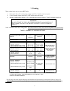
• Reduce the maximum straight pipe run by the equivalent length from Table 4 for each additional
elbow.
Example:
A vent system is planned for a BWF162 which has the following components:
2 ft vertical pipe
1 90 elbow
5 ft horizontal pipe
1 90 elbow
3 ft horizontal pipe
1 45 elbow
4 ft horizontal pipe
1 termination elbow
Since the boiler is a BWF162, all piping must be done in 3” pipe. The first 90 degree elbow and the termination
elbow are not considered. From Table 4, the equivalent length of the 3” 45 elbow is 4.5ft. The equivalent length of
the 3” 90 degree elbow is 5.5ft. The maximum allowable run of straight pipe on this system is therefore:
45ft – 4.5 ft –5.5ft = 35ft
Since the planned installation has only 14 ft of straight pipe, the planned vent system length is acceptable
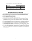
FITTING 3 INCH 4 INCH
90 DEG. ELBOW 5.5 8
45 DEG. ELBOW 4.5 4.5
HORIZONTAL CONDENSATE TEE TREATED AS STRAIGHT PIPE
NOMINAL SIZE
TABLE 4: VENT SYSTEM ELBOW EQUIVALENT
LENGTHS