


22
6) Assembly of Heat Fab Saf-T Vent:
a) Saf-T Vent General Notes:
• In general, Saf-T Vent pipe sections may not be cut. Exceptions to this are the Saf-T vent slip connector and
connections to the boiler vent collar and the VH-1 terminal. In these cases, use a sharp pair of aviation snips, an
abrasive cut-off, or a plasma cutter. See the Saf-T Vent instructions for information on cutting the slip connector.
• Orient Saf-T Vent components so that the arrows on the piping labels are in the direction of flue gas flow.
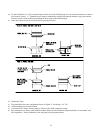
• Support horizontal piping sections at intervals of 6 feet or less.
• Vertical venting systems must be supported by at least one Heat Fab support. An additional vertical support is
required after any offset.
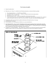
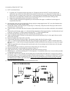
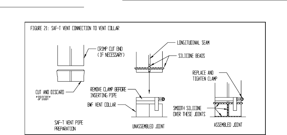
b) Start assembly of the vent system at the boiler. Remove the hose clamp shipped on the CSC vent collar. Bend the three
hose clamp tabs on this collar outward slightly.
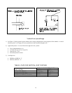
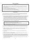
c) Cut the male “spigot” off of the first piece of pipe (Fig 21). If necessary, crimp the cut end of the pipe so that it can be
inserted at least 1” into the collar.
d) Clean the exterior of the male end of the first piece of pipe and the inside of the vent collar on the boiler with an alcohol
pad.
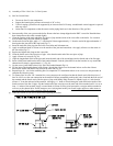
e) On the male end of the pipe, apply a ¼” wide bead of high temperature silicone approximately ½ inch from the male end
of the pipe. Also apply a ¼” bead of silicone along the first 2 ½” of the longitudinal weld.
f) Insert the male end of the pipe into the boiler vent collar until it bottoms out.
g) Apply an additional bead of silicone over the outside of the joint and smooth out (Fig 21). Also apply silicone over the
seams in the vent collar.
h) Replace and tighten the clamp on the vent collar.
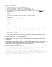
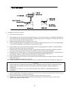
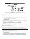
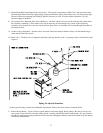
i) Clean the male end of the next piece of pipe. Also clean the female end of the first piece of pipe.
j) Apply a ¼” bead of silicone around the male end of the second piece of pipe between ¼” and 3/8” from the end of the
pipe. Also run a ¼” bead of silicone along the longitudinal welded seam from the end of the pipe to the top of the spigot
(Fig 22).
k) Align the longitudinal seams of the pipe and insert the male end of the second pipe into the female end of the first pipe
until it bottoms out.
l) With a moistened finger or flat tool, spread out any silicone that oozes out of the joint.
m) Bend the locking tabs over the locking ring as shown in Figure 22.
n) Apply silicone over any visible voids around the joint and smooth it into any crevices.
o) Repeat Steps (i) – (n) for the remaining Saf-T-Vent components. If a termination elbow or tee is used, use this procedure
to complete the exhaust system.
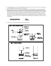
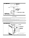
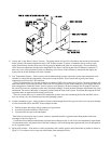
q) To join Saf-T Vent to a VH-1 terminal, cut the locking tabs off of the female end of the Saf-T Vent pipe to be joined to
the terminal. Apply a ¼” bead of silicone around the terminal connection about ¼” from the end. Slip the Saf-T Vent pipe
over the terminal and apply a second bead of silicone over the joint. Smooth the excess silicone over the joint, making
sure that there are no visible voids in the silicone. Install a pipe support or other means to prevent the Saf-T Vent pipe
from separating from the terminal.
p) Allow the silicone to cure for 24 hours before operating the boiler.