


20
5) Assembly of Z-Flex SVE Series III:
a) SVE Series III General Notes:
• Non-expanded ends of SVE Series II piping sections may be cut using aviation snips or a 24 thread per inch hacksaw.
File or sand the cut end smooth before assembling. Expanded ends may be cut to adapt the SVE Series III to the vent
collar or VH-1 terminal. See the instructions below.
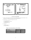
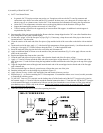
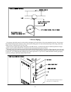
• Support horizontal piping sections at intervals of 48” or less.
• Vertical venting systems must be supported in at least one point inside the structure using a Z-Flex Fire Stop Support
or Guy Band. An additional vertical support is required after any offset.
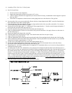
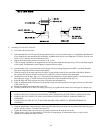
b) Start assembly of the vent system at the boiler. Remove the hose clamp shipped on the BWF vent collar. Bend the
three hose clamp tabs on this collar outward slightly.
c) Clean the exterior of the male end of the first piece of pipe and the inside of the vent collar on the boiler. Remove
dirt, grease, and moisture from the surfaces to be sealed. Dry surfaces or allow to dry thoroughly.
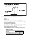
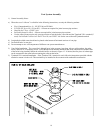
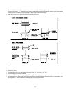
d) On the male end of the pipe, apply a ¼” wide bead of high temperature silicone approximately ½ inch from the male
end of the pipe. Apply ¼” beads of silicone along both sides of the longitudinal seam (Fig. 19).
e) Insert the male end of the pipe into the boiler vent collar until it bottoms out.
f) Apply an additional bead of silicone over the outside of the joint and smooth out. Also apply silicone over the seams
in the collar (Fig 19).
g) Replace and tighten the clamp on the vent collar.
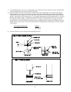
h) All other joints in the SVE Series III venting system rely on a gasket in the female end of the pipe for a proper seal.
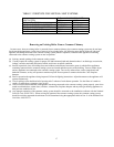
CAUTION
• MAKE SURE THAT GASKET IS IN POSITION AND UNDAMAGED IN THE FEMALE END OF THE PIPE.
• MAKE SURE THAT BOTH THE MALE AND FEMALE PIPES ARE FREE OF DAMAGE PRIOR TO
ASSEMBLY.
• IF MALE END OF PIPE IS CUT, IT MUST BE SQUARE AND CAREFULLY DEBURRED PRIOR TO
ASSEMBLY.
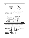
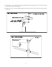
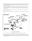
i) Align the longitudinal seams of the pipe. Insert the male end of the second pipe into the female end of the first pipe as
far as it will go (at least 1.75 inches). See Figure 20.
j) Tighten the locking band with a nut driver to a torque of between 40 in-lbs and 50 in-lbs.
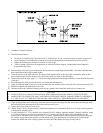
k) Repeat Steps (i) and (j) for the remaining SVE Series III components. If a termination elbow is used, use this
procedure to complete the exhaust system.