


88
APPENDIX C – VALVE AND ACTUATOR MOUNTING INSTRUCTIONS
Application
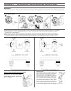
For use with ESBE ½” to 6” 3-Way and 4-Way rotary valves for mixing and diverting applications. Use with 24Vac 3-point “floating” signal controller.
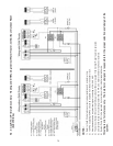
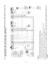
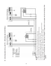
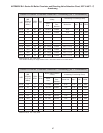
Mounting the Motor
1. Place drive sleeve onto shaft and secure with bolt . Check that the valve is in mid-position (sleeve pointer set to position 5 on scale plate).
2. Mount threaded stud in one of the threaded holes. For 1½” and 2" valves replace one of the cover bolts with the threaded rod. Tighten
mounting piece onto threaded rod.
3. Mount handle over drive sleeve set pointer to 5 on the scale plate. Handle must be mounted opposite to the pointer of the drive sleeve.
4. Mount motor onto sleeve so that the mounting piece m fits into the locking piece o. Push locking piece to lock in place. Labels are supplied
to indicate the direction of rotation. Determine the direction of rotation and mount the correct label under the plastic front cover of motor.
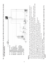
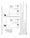
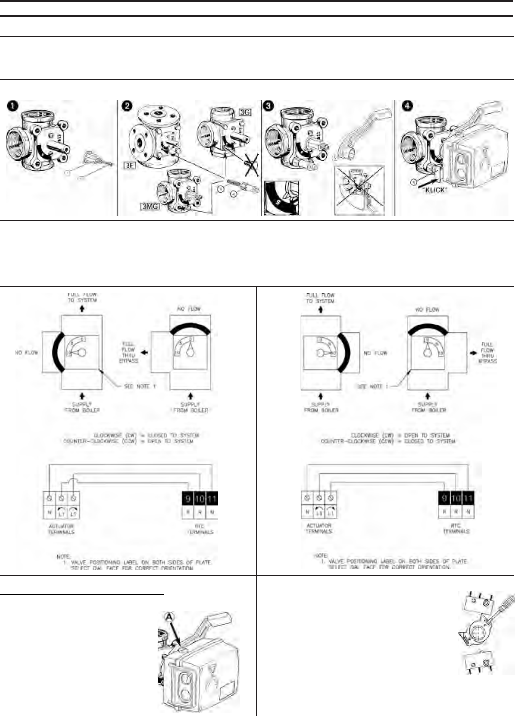
Manual Operation
Always disconnect power before operating by hand. Note
position of drive sleeve pointer to be returned to. Depress
the gray button, “A”, on the side to release
the handle. The valve can now be operated
manually. Never manually operate when
gears are engaged.
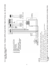
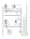
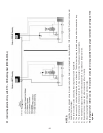
Adjusting Cams
The position of the cams is changed by fitting a screw-
driver in the slot and moving the cam to the desired
position.The topmost cam operates the auxiliary
switch (upper switch – NOT USED). The middle and
lower cams determine the degree of rotation (30° to
180°). To access, remove the actuator cover to gain
access to the middle and lower cams.The valve rota-
tion must be set before operation can begin. Adjust
the cam so that each end switch is made when the
valve is fully open (pointer towards “0”) and when the
valve is fully closed (pointer towards “10”). Depress
the “Test” switch on the RTC control to test for proper valve operation.