


37
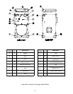
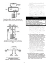
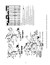
Figure 32: Series 24 Minimum Piping Recommendation 2 - Water Boiler
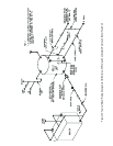
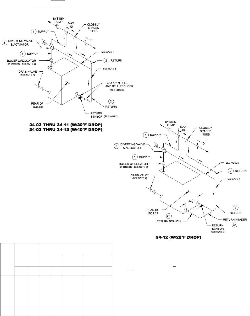
Figure 33: Series 24 Minimum Piping Recommendation 3 - Water Boiler
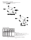
Recommendation 3 — Use when:
• system return water is less than 135° F for prolonged periods of time
• system flow does impact flow through the boiler(ie. zoning, mixing)
• requires addition of RTC Return Temperature Control and accessories
NOTES:
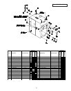
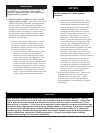
1. All piping is schedule 40.
2. Pipe sizes listed are based on a 20°F or 40°F differential (temperature drop).
Select one to match application.
3. When specifi
ed return piping size is less than 3”, install 3” X 12” nipple and appropriate
size bell reducer directly into boiler return tapping as shown.
4. Drain valve — ball valve preferable, gate valve acceptable alternative
(supplied by others).
- Minimum valve size per ASME code is 3/4” NPT
5. Maximum linear feet of pipe from 3-way bypass port to sensor location = 11 feet.
Bypass line shall be the same diameter as return Á
6.
Minimum linear feet of pipe from point of mixing (where bypass meets return line) to
sensor location = 4 feet.
7. Install special 3” x 12” nipple with 1/4” NPT side tapping closest to boiler. Where
applicable, use bell reducer to adapt to recommended return pipe size.
8. Proper boiler circulator sizing is listed in Appendix B.
Pipe Sizing and Notes
LEDOM
YLPPUS
GNIPIP
)NI(EZIS
)1(
)NI(EZISGNIPIPNRUTER
)2(NRUTER
NRUTER
REDAEH
)A2(
NRUTER
HCNARB
)B2(EZIS).YTQ(
F°02
PORD
F°04
PORD
F°02
PORD
F°04
PORD
F°02
PORD
F°02
PORD
30-42
40-42
50-42
60-42
70-42
80-42
90-42
01-42
11-42
21-42
2
2
2
2/1-2
2/1-2
2/1-2
3
3
3
4
2/1-1
2/1-1
2/1-1
2/1-1
2
2
2
2/1-2
2/1-2
2/1-2
2
2
2
2/1-2
2/1-2
2/1-2
3
3
3
4
2/1-1
2/1-1
2/1-1
2/1-1
2
2
2
2/1-2
2/1-2
2/1-2
—
—
—
—
—
—
—
—
—
3
—
—
—
—
—
—
—
—
—
3)2(