


73
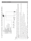
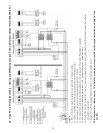
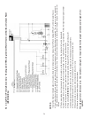
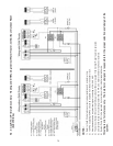
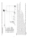
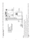
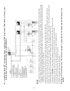
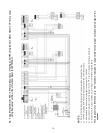
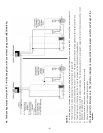
NOTES:
1) Refer to the I&O to determine correct valve orientation and actuator wiring.
2) 120 VAC supplying the RTC should be separate from the burner/boiler circuit.
3) Heat demand can be any electrical signal consisting of 24 – 240 VAC.
4) The Outdoor Sensor (S3) and the Mix Supply Sensor (S2) are required if the Outdoor Reset feature is selected.
5) Use isolation relays for circulators greater than 1/3 HP. Use motor starters for 3 phase circulators.
6) Connect the Tankless Aquastat (A1) if you are not using a storage tank. If you are using a storage tank with the tankless heater than using the
storage tank aquastat (A1).
7) System Pump (P3) to be operated by zone relay or other installer supplied device.
This diagram is for reference only. The installer or designer is responsible for the proper selection and design of the
system.
A2. 3-way RTC in Primary/Secondary – Heating and DHW using Tankless Coils; with/without Outdoor Reset (ELECTRICAL)