


44
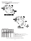
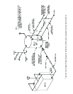
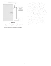
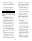
Figure 40b: Water Boiler - Pressure Relief Valve
Hook-Up
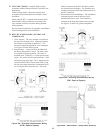
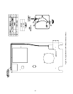
placement. The 14 gauge mounting bracket must
be attached to the jacket first using four (4) #8 x ¾”
drill point sheet metal screws.
One may find it easier to install some of the conduit
connectors with their corresponding conduit runs onto
the RTC back panel before mounting to the bracket.
The actual controller can and should be removed from
the back panel during the mounting process. This
will eliminate the potential for accidental damage to
the controller.
The RTC back panel is mounted onto
the bracket with (4) #8-32 x ½” type F, Phillips Pan
head screws supplied with the controller. The middle
3 rear knockouts should be used before utilizing the 5
knockouts exiting the bottom of the control. Depending
on the final configuration, most of the controller
connections could be used. Typically, the return sensor,
actuator control and boiler pump exit the rear of the
controller.
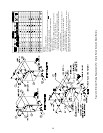
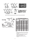
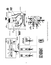
Wire the RTC controller to the various components
as shown below. The “Mix” and “Outdoor” sensor
are optional and must be connected if outdoor reset
function is desired. The outdoor reset function on
this controller cannot be used in a multiple boiler
application. A boiler sequencer must be used when an
outdoor reset feature is required in a multiple boiler
application.