


10
SECTION I - GENERAL INFORMATION (CONTINUED)
A. INSPECT SHIPMENT carefully for any signs of
damage.
1. ALL EQUIPMENT is carefully manufactured,
inspected and packed. Our responsibility ceases
upon delivery of crated boiler to the carrier in good
condition.
2. ANY CLAIMS for damage or shortage in shipment
must be filed immediately against the carrier by the
consignee. No claims for variances from, or short-
age in orders, will be allowed by the manufacturer
unless presented within sixty (60) days after the
receipt of goods.
3. Make sure that appropriate items on the Master Parts
List (pg 59) are all on hand.
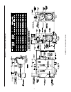
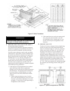
B. LOCATE THE UNIT
1. RECOMMENDED SERVICE CLEARANCE
- Locate the unit in the boiler room so as to
provide ease of venting and adequate clearance
for maintenance, serviceability, and installation of
piping. Refer to Figure 1 for boiler dimensional
data.
FRONT — Provide 43” service clearance for
removal, maintenance, and servicing of burner and
controls.
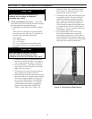
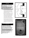
REAR — Provide a minimum clearance from the
boiler jacket for access to flame observation port,
rear flue damper and vent piping, relief valve, and
boiler return piping. See Table III.
LEFT SIDE — Provide a minimum clearance from
the boiler jacket of 26” for cleaning of flueways and
installation and removal of tankless heater(s).
RIGHT SIDE — Provide a minimum clearance from
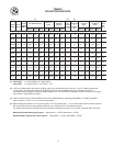
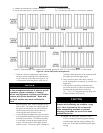
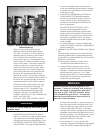
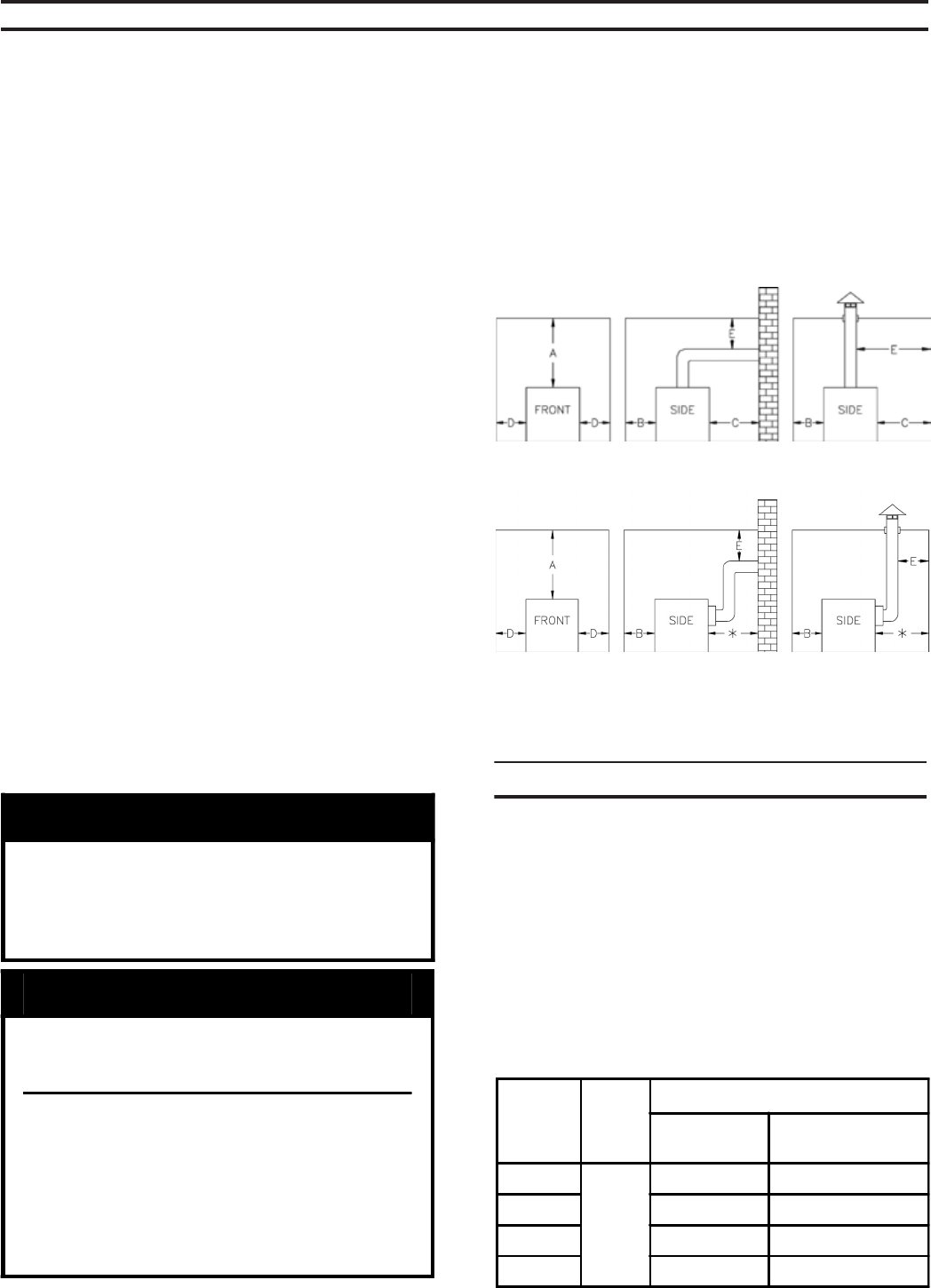
Table II: Minimum Clearances To Combustible
Materials (Inches)
Boilers with Top Flue Outlet
Boilers with Rear Flue Outlet
Flue
Outlet
Size
Top
Flue
Outlet
Rear Flue Outlet
Combustible
Surfaces
Non-Combustible
Surfaces
7" Dia.
18"
37" 22"
8" Dia. 38" 23"
10" Dia. 40" 25"
12" Dia. 43" 28"
NOTICE
Recommended clearance for service may be
reduced to minimum clearance to
combustible material. However, increased
service and maintenance difficulty will
result.
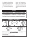
WARNING
Boiler is suitable for installation on
combustible floor. Do not install boiler
on carpeting.
Floor construction should have
adequate load bearing characteristics
to bear the weight of the boiler filled
with water (see Table 1). A boiler
foundation similar to the one shown in
Figure 2 is recommended if the boiler
room floor is weak or uneven or if a
water condition exists.
A
evobA
B
tnorF
C
raeR
D
sediS
E
rotcennoCtneV
6 42 6 6 81
sseccaotecnaraelcecivresdednemmoceRrofIIIelbaTeeS*
reliobforaer
lanoitaNnaciremAhtiwylpmocsecnaraelcdetsiL:1ETON
.tnempiuqegninrubliofonoitallatsnI,13APFN/ISNAdradnatS
htiwsmoornidellatsniebnacsreliob42seireS:2ETON
detsiL.evobadetsilsalairetamelbitsubmocmorfsecnaraelc
tesolcroevoclarofdecuderebtonnacsecnaraelc
.snoitallatsni
,lairetamelbitsubmocotsecnaraelcdecuderroF:3ETON
evobaehtnidebircsedsadedivorpebtsumnoitcetorp
.dradnats13APFN/ISNA
Table III: Recommended Rear Service Clearance
the boiler jacket of 12”.
T
OP — Provide a minimum clearance from the
boiler jacket of 24”
2. FOR MINIMUM CLEARANCES to combustible
materials, See Table II.
3. PROVIDE ADEQUATE FOUNDATION for the
unit. Refer to Figure 2.