


33
WARNING
Return water cannot be lower than 135°F for prolonged periods of time. Operation under these
conditions will result in sustained condensing within the combustion chamber and potentially
reduce boiler longevity.
In addition, the return water cannot be introduced into the boiler if it is more than 40°F less than
the idle boiler temperature. Continued operation under these conditions may result in
premature boiler failure through thermal shock.
Example
: A boiler that has been idle for some time since the last heat demand cycle may have
it's boiler water temperature reduced to 150°F. The return temperature from the next zone
activation cannot be less than 110°F.
If the above conditions exist, an RTC system must be installed to protect the boiler from
sustained condensing operation and thermal shock.
WARNING
A hot water boiler installed above radiation
level must be provided with a low water
cutoff device as part of the installation.
1. HOT WATER HEATING - This boiler must be
installed in strict accordance to the instructions
found in this installation manual. Deviations
from these installation instructions may void
manufacturer’s warranty. See warning below
to determine the use of the RTC. A Return
Temperature Control (RTC) may be provided to
protect the boiler from thermal shock and sustained
condensing operation. In addition, a properly
selected boiler circulator and diverting valve, along
with the return sensor, must be installed when using
the RTC. A number of typical Crown applications
have been added to the appendix (Appendix A).
Select the appropriate application before proceeding.
a. Parallel Piping Systems – An existing parallel
piping system may be used, provided the return
water is not below 135°F for prolonged periods
of time, and the return water temperature is
not more than 40°F less than the idle boiler
temperature (see warning below). A flow
analysis should be performed to determine the
flow through the boiler when the minimum (and
smallest) and maximum number of zones are
activated. A sufficient flow through the boiler
should be maintained to assure a maximum of
40°F difference between the boiler supply and
return.
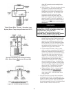
If the conditions above cannot be met, then
parallel piping systems must be converted to a
primary/secondary arrangement, de-coupling
the system pump from the boiler loop. The
system pump cannot influence the flow through
the boiler(s) in a primary/secondary piping
arrangement. The concept must be for the boiler
loop to inject heat into a primary loop, provided
the return water into the boiler is at least 135°F.
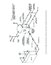
A by-pass containing two closely spaced tees
must be installed to de-couple the boiler loop
from the primary loop (see Figure 30). Care
must be taken to avoid dead heading the
system pump. Conversions should be reviewed
and approved by a Consulting Engineer or
other qualified professional to avoid system
deficiencies.
b.
Primary/Secondary Piping – Boiler(s) must
be installed into a heating system that is
(are) designed as a primary/secondary piping
arrangement when the flow through the boiler
cannot be maintained to provide a 20°F - 40°F
difference between the boiler supply and
return. When using an RTC, the boiler loop
contains a boiler, boiler circulator and diverting
valve, along with the return temperature control
(RTC) and return sensor. The diverting valve
consists of a 3-way valve, positioned through
the use of an electronic actuator. The boiler loop
injects heat into the primary loop, provided the
temperature of the boiler return water is greater
than 135°F. If the temperature is below 135°F,
the diverting valve closes, recirculating the
boiler water until it has heated above the 135°F
minimum limit. The supply and return of the
boiler loop is connected to the primary loop
through the use of two closely spaced “Tees”, at
a maximum branch centerline distance of 4 times
the primary loop diameter (4 x D Max.) The
RTC provides a signal to the actuator based on
the absolute water temperature and the rate of
change in water temperature.
c. Multiple Boilers – Multiple boilers are installed
the same as single boiler installations. Each
boiler loop will contain it’s own boiler circulator,
diverting valve, RTC and return sensor (see
Appendix A). Commonly available sequencers
can be used in conjunction with the Return
Temperature Control by energizing the control’s
heat demand circuit. The outdoor reset feature
of the sequencer must be used in multiple
boiler installations. The outdoor reset feature