


23
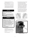
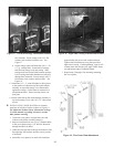
C. MOUNT REAR OBSERVATION PORT COVER
Refer to Figure 16.
1. With the silastic sealant, secure the 3/16” diameter
rope gasket into the groove around the perimeter of
the rear observation port cover.
2. Mount the rear observation port cover onto the rear
section (with the word “Top” in the upright position)
using the four (4) 5/16” - 18 x 1” lg. cap screws and
flat washers provided.
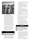
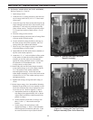
D. INSPECT ALL BOILER SEALS
1. A visual inspection should be made of all sealed
joints and repairs made as necessary. Darken
the boiler room and place a light source in the
combustion space and canopy to observe any gaps
or open seals. Poor seals must be repaired and
rechecked before continuing.
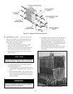
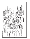
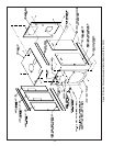
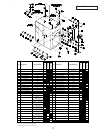
E. JACKET ASSEMBLY - See Figure 22 for Jacket
Assembly Details.
1. Open jacket carton and jacket hardware package.
Unless otherwise stated, all jacket components are
fastened with #8 x ½” hex head sheet metal screws.
Do not drive sheet metal screws tight until jacket
assembly is complete.
2. On boilers with rear flue outlet damper assembly,
remove square knockout from jacket rear panel. To
remove knockout, use a single hacksaw blade with
handle or aviation snips to cut metal tabs between
slotted holes.
3. Attach jacket front panel to front section and jacket
rear panel to back section using the eight (8) #10
x ½” self tapping screws. Tighten these screws
securely.
4. Attach jacket lower tie bar panel (approximately
5-5/8” high) to the bottom of the jacket front and
rear panels using four (4) sheet metal screws.
Repeat for opposite side.
5. Attach jacket upper tie bar panel (approximately
4-1/8” high) to the top of the jacket front and rear
panels using four (4) sheet metal screws. Repeat for
opposite side.
6. Jacket Top Panel Attachment
a. On boilers with top flue outlet damper assembly,
remove octagon shaped knockout. To remove
knockout, use a single hacksaw blade with handle
or aviation snips to cut metal tabs between
slotted holes.
b. Remove knockout(s) for necessary supply piping
in a similar manner
.
c. Attach jacket top panel to the front panel, rear
panel and upper tie bar panels with sheet metal
screws.
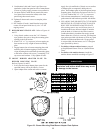
7. Install Jacket side Panels
a. Snap black thumb hole bushings into all side
panel holes.
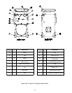
b. Use the left side panel and right side panel usage
charts to determine correct positions of side
panels. The three (3) digit panel identification
numbers shown in the charts are also stamped
along the bottom edge of each panel. Refer to
Figures 20 and 21.
c. Rearward and Intermediate panels have reverse
bend flanges on one side of panel. These panels
must be installed prior to forward panels.
NOTICE
To install
multiple side panels, start at the
rear of boiler and work forward. To remove
panels, reverse order of assembly.
d. If boiler is equipped with tankless heaters they
should be installed at this time if they were not
installed for hydrostatic test outlined on Page 18.
e. Install right side panels into position by inserting
top of panel into ‘U’ shaped channel, pushing
bottom of panel in toward boiler, and sliding
panel down into ‘J’ shaped channel. Repeat
procedure until all right side panels are in place.
f. Remove the knockouts necessary for tankless
heater operation on left side panels.
g. Install left side panels, using the same procedure
used to install the right side panels.
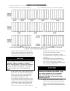
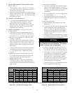
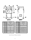
Figure 20: Left Side Panel Usage Chart
Figure 21: Right Side Panel Usage Chart
PANEL 1 PANEL 2 PANEL 3 PANEL 4 PANEL 5 PANEL 3 PANEL 2 PANEL 1
24-03 L10 L5 - - - 24-03 - - R15 (SINGLE)
24-04 L10 L11 - - - 24-04 - - R21 (SINGLE)
24-05 L10 L17 - - - 24-05 - - R27 (SINGLE)
24-06 L10 L18 L5 - - 24-06 - - R33 (SINGLE)
24-07 L10 L18 L11 - - 24-07 - R15 R24
24-08 L10 L18 L17 - - 24-08 - R21 R24
24-09 L10 L18 L18 L5 - 24-09 - R27 R24
24-10 L10 L18 L18 L11 - 24-10 - R27 R30
24-11 L10 L18 L18 L17 - 24-11 - R33 R30
24-12 L10 L18 L18 L18 L5 24-12 R21 R24 R24
JACKET LEFT SIDE PANEL USAGE CHART RIGHT SIDE PANEL USAGE CHART
BOILER
MODEL
BOILER
MODEL
SINGLE / MULTIPLE RIGHT SIDE PANELS*MULTIPLE LEFT SIDE PANELS*
*NOTE: TO INSTALL MULTIPLE SIDE PANELS, START AT THE REAR AND WORK FORWARD. TO REMOVE PANELS, REVERSE ORDER OF ASSEMBLY.
REAR OF BOILER
FRONT OF BOILER
FRONT OF BOILER
REAR OF BOILER