


70
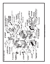
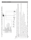
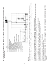
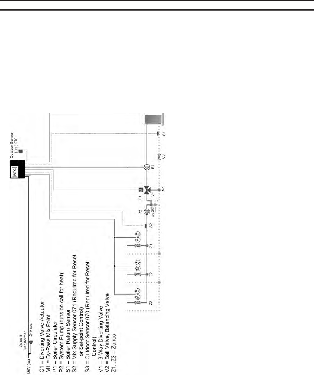
A1. 3-way RTC in Primary/Secondary – Heating Only/No DHW; with/without Outdoor Reset (MECHANICAL)
NOTES:
1) Install the boiler as indicated above for systems where return temperatures may be less than 135F and heating application only.
2) The Outdoor Sensor (S3) and the Mix Supply Sensor (S2) are required when the Outdoor Reset feature is selected. The mix sensor must be installed
10 pipe diameters downstream of the system pump, in the primary loop. The mix sensor must be secured to the surface of the pipe using a wire tie or
similar device.
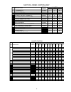
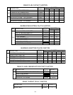
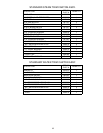
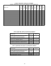
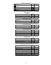
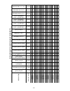
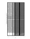
3) The by-pass piping, diverting valve and boiler circulator must be sized using the sizing charts found in Appendix B.
4) Closely spaced tees must connect the branch to the larger header. The Tee centerlines must be no greater than 4 times the larger header pipe diameter.
5) The diverting valve, V1, must be no greater than 11 linear feet of pipe from the Return Sensor, S1.
6) There shall be a MINIMUM of 4 linear feet of pipe between the By-pass Mix Point, M1, and the Return Sensor, S1.
7) The balancing valve in the boiler return line, V2, may be necessary in low head by-pass loop applications.
8) Expansion tanks, air scoops and other components left out for clarity.
9) Observe all applicable plumbing and electrical codes.
This diagram is for reference only. The installer or designer is responsible for the proper selection and design of the sys-
tem.
SECTION VIII - APPENDIX