


25
8. Combination Label and Crown Logo Plate were
attached to jacket front panel at time of manufacture.
If loose or peeling, apply pressure to reset adhesive.
9. On steam boilers, attach lowest permissible water
level plate (from steam trim carton) to the front
panel using sheet metal screws.
10. Tighten all sheet metal screws to complete jacket
assembly.
11. RTC Bracket (if used)- install bracket in top right
corner of front panel with four (4) #8 x 3/4” self
tapping screws.
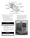
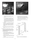
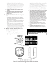
F. BURNER MOUNTING PLATE - Refer to Figures 16
and 23.
1. Using silastic sealant, secure the 3/16” diameter
rope gasket to the groove along the mounting plate
opening in the front section.
2. Install 5/16” x 1” lg. cap screw in lower tapping on
front section to carry weight of burner mounting
plate.
3. Engage bottom slot on burner mounting plate with
matching bolt in bottom tapping of front section.
Align mounting holes and fasten the mounting plate
to the boiler sections with seven (7) remaining 5/16”
cap screws and washers. Fully tighten all bolts.
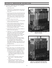
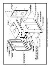
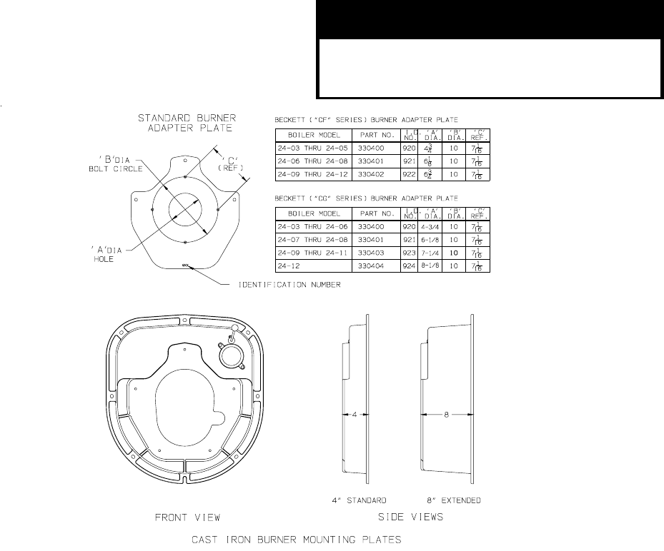
G. MOUNT BURNER ADAPTER PLATE TO
BURNER MOUNTING PLATE.
Refer to Figures 16 and 23.
1. In all cases the burner adapter plate carton for the
specified burner will be provided by Crown.
2. Open Adaptor Plate carton and remove contents.
CAUTION
Failure to properly fill all gaps between the
insulation and burner blast tube may result
in damage to the burner
Apply four (4) small dabs of silastic on rear surface
of adapter plate to temporarily hold gasket in
place. Hold adapter plate in position against burner
mounting plate, align holes and secure with five (5)
3/8” lock washers and 3/8” x 7/8” lg. cap screws.
3. Follow burner manufacturer’s instructions using
gasket material and hardware provided with burner.
4. USE A HOLE SAW OR KNIFE TO CUT BURNER
MOUNTING PLATE INSULATION TO MATCH
HOLE SIZE ON BURNER ADAPTER PLATE.
After cutting, remove any and all loose pieces of
insulation which may become lodged or interfere
with the head of a burner air tube after insertion.
Confirm that hole in insulation fits snugly around
burner blast tube. If hole is oversized, use fiberglass
rope gasket provided with burner to fill in any space
between insulation and blast tube. If rope gasket
is not provided with the burner, use 3/8” fiberglass
rope (provided by others).
5. For boilers without tankless heaters, proceed
to Step H (Install Steam Trim) or I (Install Water
Trim).
6. For boilers with tankless heaters, install the
tankless heater manifolds according to Figure 37.
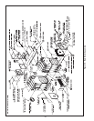
Figure 23: Burner Mounting Plate/Burner Adapter Plate Options