


17
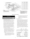
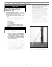
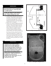
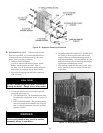
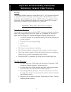
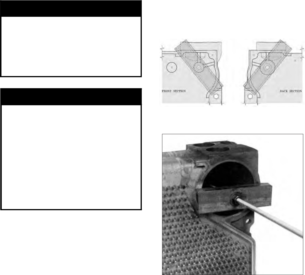
Figure 11: Center Section Channel Block Position
(Partial Block Draw-Up)
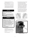
Figure 10: Front and Rear Section Channel
Block Positions (Hydraulic Draw-up)
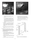
CAUTION
Do not apply pressure directly on threaded
tappings on front and rear sections with
draw-up channels during assembly
procedures.
Rods should be approximately centered in
openings so that rods and couplings (when
used) do not drag on pipe thread in end
section tappings.
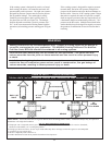
WARNING
READ THE STATEMENTS BELOW BEFORE
ATTEMPTING TO USE HYDRAULIC EQUIPMENT.
*
*
*
*
Re
lease pressure in ram pumps before
attempting to remove clamps.
Do not stand in line with draw-up rods at
either end when hydraulic pressure is
being applied. As a safety measure,
ends of draw-up rods should be covered
while sections are being drawn in case
rods should snap while under tension.
Do not operate ram against draw-up
coupling.
Do not operate pump after ram has
reached stroke limit.
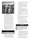
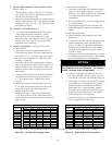
e. Draw-Up Sections
Use hydraulic rams to draw up sections by
applying pressure alternately on the draw-up
rods. When rams reach stroke limit, release
pressure in ram pumps and then move clamps to
new position.
f. Continue to draw-up until all sections make
contact at the ground joints.
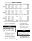
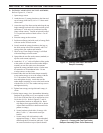
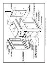
g. After all sections have been drawn up, but before
removing the hydraulic rams and draw-up rods,
the 9¾” long tie rods must be installed.
The large draw-up rod lugs with dual holes
are cast in the four (4) corners of each casting.
Starting with the upper holes in the back section,
install four (4) 5/8” x 9¾” long tie rods along
with washers and nuts. Continue installing the
tie rods alternating from the upper to lower set
of holes in draw-up lugs until front section is
secured. Be certain that all sections are drawn
up IRON TO IRON at all three nipple ports.
h. Excess length of draw-up rods must not extend
beyond front and rear section. To ensure proper
fit of jacket, adjust accordingly. Tighten all tie
rod nuts until finger tight. Then tighten them
an additional ½ turn with a wrench to prevent
section damage to thermal expansion.
tapped holes in the front section. Be sure to
screw draw-up rods into couplings far enough to
prevent stripping threads.
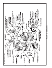
d. Place a 3” x 12” lg. steel channel on each end of
the upper draw-up rod and a 3” x 8½” lg. steel
channel on each end of the lower draw-up rods.
Refer to Figures 10 and 11 for proper placement
of channel block during assembly procedures.
Install nuts and washers on one end of the draw-
up rods and the hydraulic rams, washers and
draw-up rod clamps on the other. See Figure 13.