


48
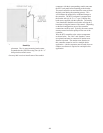
of installation.
5. ON WATER BOILERS WITH TANKLESS
HEATERS, set low limit operating control dial at
190°F and high limit dial 210°F. Operating control
must be a minimum of 20° below high limit setting.
Set differential at 25°.
D. ADJUST BURNER according to the Burner Manual.
1. FLAME FAILURE
The Series 24 boiler controls operate the burner
automatically. If for unknown reasons the burner
ceases to fire and the reset button on the primary
control is tripped, the burner has experienced
ignition failure. Before pressing the reset button,
call your serviceman immediately.
WARNING
Do not attempt to start the burner when
excess oil or gas has accumulated in the
combustion chamber, when the unit is full
of vapor, or when the combustion chamber
is very hot.
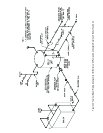
E. RETURN TEMPERATURE CONTROL: Initial
Set-Up and Operation – The return temperature
control (RTC) is an important part of the overall boiler
system. The primary function of the RTC is to protect
the boiler from thermal shock and sustained flue gas
condensation. The RTC monitors the temperature of
the water returning into the boiler through a return
sensor. The RTC controls the 3-way diverting valve
mounted on the supply of the boiler to prevent return
water less than 135º F from entering the boiler. The
boiler circulator provides constant and minimum flow
through the boiler during every heat demand. Prior
to the start of any boiler cycle, the diverting valve is
closed to a full by-pass condition, forcing 100% boiler
water re-circulation. The diverting valve opens and
will continue to open provided the return sensor is
satisfied. Conversely, large temperature drops will
close the diverting valve to a position as to prevent
low temperature return water. The RTC along with
the ancillary components must be properly installed
as identified in Section III, if there is any possibility
of system return water temperature less than 135°F. A
detailed description of the controller and it’s features
can be found in the RTC Installation and Maintenance
Manual.
1. Initial Start-up - Upon initial start-up, the control
will be energized, identifying the control name and
revision on the LED display. If wired properly, the
control should be energized at all times. The RTC
circuit should be supplied from a different source
than the burner or boiler circuit. The RTC control
should be energized at all times.
2. Testing – The RTC should be tested on initial start-
up, as well as during any troubleshooting exercise.
Depressing the test button will activate a test
sequence and energize the red test light on the front
of the control. Each of the controllers outputs and
relays will be energized and tested. One may pause
the test sequence at any time by depressing the test
button. See the RTC Installation & Maintenance
Manual for a detailed description of the sequence
and the potential error messages.
a. Return Sensor - The return sensor must be
properly connected or an error message will be
displayed. Both a short and an open circuit in
the sensor circuit will cause an error message to
be displayed and the valve will be moved to a
partially open position until the error is resolved.
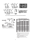
b. Valve Actuator – During the valve actuator test
sequence, confirm that the valve travels through
90 degrees of rotation from a full closed position
to a full open position. The pointer on the shaft
must rotate from “10” to “0” respectively.
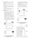
3. Adjust Setpoints – The RTC must have a number of
setpoints adjusted for proper operation. Below is
a summary, however see the RTC Installation and
Maintenance Manual for more details. To activate
the ADJUST menu, simultaneously depress and
hold the Item, and buttons. ADJUST will
appear in the upper right hand corner of the LED
display.
a. ROOM - Set desired room temperature. This
will provide parallel shift to heating curve.
OUTDR DESIGN OFF
b. MIX TARGET – This represents a fixed target
supply temperature when the outdoor reset
feature in NOT selected. (OUTDR DESIGN =
OFF) Set the MIX TARGET temperature to the
designed boiler supply temperature. Example:
If the boiler loop is designed to supply hot water
to the system at 180ºF, set the MIX TARGET
to 180ºF. This is also the same as the operating
aquastat set point. The mix target is adjustable
from 60°F to 200ºF. The default setting is 180°F.
NOTE: This function is only for applications
where the mix sensor is installed.
c. MIX DSGN – Mix design temperature represents
the design heating system supply temperature
when the outdoor reset feature is selected.
(OUTDR DESIGN = ON) This represents the
design of the system loop. If unsure of the
original design temperature, set the MIX DSGN
to the same temperature as the boiler operating
aquastat, typically 180ºF. The MIX DSGN is
adjustable from 70°F to 210ºF. The default
setting is 180°F.
d. OUTDR DSGN – The outdoor design
temperature represents the value used in the
heat loss calculations, when the outdoor reset
feature is selected. (OUTDR DESIGN = ON) If
this value is unknown, use the value found in