


6
Eclipse Veri-Flame Instruction Manual 818-2/02
Optional Features .................................................................................................
16
Pilot Test Mode Sequence ..............................................................................
16
Air Switch Input Hold .....................................................................................
16
Remote Display & Power Supply..................................................................
16
Status Lights & Push-buttons..............................................................................
17
Interlocks Closed .............................................................................................
17
Air Failure ..........................................................................................................
17
System Error .....................................................................................................
17
Burner On..........................................................................................................
17
Flame Failure .....................................................................................................
17
Low Fire..............................................................................................................
17
High Fire .............................................................................................................
17
Auto.....................................................................................................................
17
Test/Reset...........................................................................................................
17
System Installation ...................................................................................
18
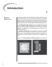
Introduction............................................................................................................
18
Interlocks and Limit Switch Input .....................................................................
18
Combustion Air Switch Input.............................................................................
18
Ignition Wiring........................................................................................................
18
Low Fire Input........................................................................................................
19
Main Valve Closed switch ....................................................................................
19
High Fire Input .......................................................................................................
19
Remote Reset ........................................................................................................
19
Remote Display & Power Supply.......................................................................
19
Purge and No Purge Wiring Diagram (Figure 5.1)........................................
20
Modulation Wiring Diagram (Figure 5.2) ........................................................
20
Sensor Installation ....................................................................................
24
Introduction............................................................................................................
24
Sensor Wiring.........................................................................................................
24
Flame Rods .............................................................................................................
25
Scanners...................................................................................................................
25
Scanner Sighting Considerations .......................................................................
25
Test Procedures...........................................................................................
26
Introduction............................................................................................................
26
Flame Signal Strength ...........................................................................................
26
Minimum Pilot Test................................................................................................
26
Pilot Flame Failure Test ........................................................................................
27
Main Flame Failure Test ........................................................................................
27
Spark Sighting Test.................................................................................................
27
Limits & Interlock Tests .......................................................................................
27
4
6
7
5
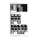
Typical Connections for all Models (Figure 5.3) ............................................
21