


21
Eclipse Veri-Flame Instruction Manual 818-2/02
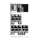
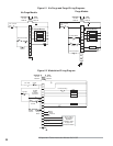
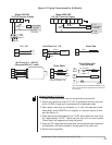
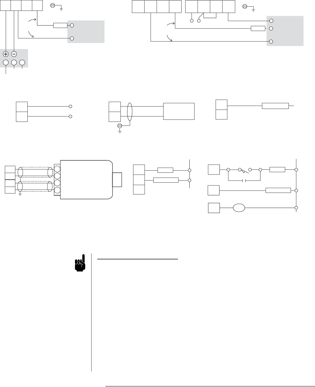
Notes for Figures 5.1, 5.2 & 5.3:
1. Ground, shielding and conduit must not be connected to terminal S2.
2. Control circuit wires must meet 90°C (194°F) specification minimum and must
be No. 16 AWG or larger and in accordance with all applicable codes.
3. Flame sensor wires must be individually run in their own separate conduit;
flame sensor wires CANNOT be run together in a common conduit or wire-
way (See Section 6).
4. Flame signal should read between 4 and 10 VDC with a digital volt meter. Drop
off is approximately 4.0 VDC. Positive test jack point is on the cover marked
“Flame Signal” with negative point being the ground.
5. Purge time, TFI, intermittent/interrupted pilot, and recycle/non-recycle selections
are made with a DIP switch located on the rear plate of the control unit.
6. Neutral must be grounded.
Figure 5.3
Typical Connections For All Models
24V G GTx Rx
Flame Signal
Test Jack
To S2
Veri-Flame
24 VDC Remote Display
PLUG
Cable
#20318
120/240VAC
NG
Power
Supply
#20317
12V
+
Tx
Rx
120 VAC Remote Display
12V
-
120V
N
R1 R2
120V
L
G
Flame Signal
Test Jack
To S2
Veri-Flame
To 1
PLUG
Cable
#20318
to 120 VAC
Blue
Flame RodU.V./ I.R.
Blue (Signal)
Yellow (Neutral)
U.V
or
I.R.
Flame Rod
S2
S1
S2
S1
Solid State U.V./ I.R.
White
Black
S2
S1
G
Shield
Scanner
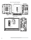
3
4
5
MAIN
IGNITION
Neutral
Direct Spark
MAIN
IGNITION
Neutral
CR
4
3
5
CR
Direct Spark with
Low Fire Start
Note: Intermittent pilot must
be selected, DIP-SW2 = ON
Note: Intermittent pilot must be selected, DIP-SW2 = ON
CR is a control relay used to bypass the low fire switch afte
r
the burner is lit.
Low Fire Proving
1
2
S2
S1
A
B
C
D
Self Check U.V. 5602-91
(Requires 5602-91-7 cable)
Model 5602 DB
Model 5602 DBP