


19
Eclipse Veri-Flame Instruction Manual 818-2/02
Ignition Wiring
Low Fire Input
Main Valve
Closed Switch
High Purge Input
Remote Reset
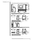
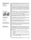
Route ignition wiring a sufficient distance from all sensors and other low volt-
age wiring to avoid electrical interference, which may cause erratic operation
of the Veri-Flame system. Keep the high voltage wire run from the ignition trans-
former as short as possible. The best condition is to mount the ignition trans-
former close to the burner and keep a low impedance path from the burner
ground to the case of the transformer. Make sure the high voltage lead and
ground return paths do not create a loop antenna around the Veri-Flame and
sensor wiring.
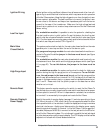
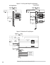
For modulation models: it is possible to wire the system for checking low
fire start position prior to pilot ignition. To use this feature, the low fire start
switch must be connected between terminal 3 and the pilot valve (see Figure
5.2). On direct spark burners, a by-pass contact must be wired around the low
fire switch, see relay and contact CR in Figure 5.3.
The system can be wired to check for the main valve closed switch on the main
gas valve prior to start-up and after the end of the burner cycle.
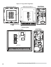
For purge and no purge models: the main valve closed switch must be con-
nected to Terminal V and the jumper in the base must be cut (see Figure
5.4 on page 22).
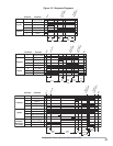
For modulation models: the main valve closed switch must be wired in se-
ries between the air flow switch and the high purge damper switch (see Figure
5.1 on page 20). To use this feature, the jumper in the base must be
cut.
For modulation models: the system can be wired to check for high purge
position during the high fire purge portion of the sequence. To use this fea-
ture, the red jumper in the base must be cut and the high purge position
switch must be connected from terminal 6 to D. If this feature is not used, the
jumper in the base remains intact or a jumper must be installed between termi-
nals 1 and D. Please note that the yellow jumper on the base has no effect
whether cut or intact.
This feature permits remote mounting of a switch to reset the Veri-Flame. To
use this feature, a normally closed remote reset switch must be wired so power
is interrupted to terminal 1. When it is depressed or actuated, the connection
to terminal 1 is momentarily interrupted and resets the Veri-Flame.
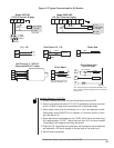
Identify the model of remote display (see page 11) and wire according to figure
5.3. Mount through a ¼ DIN cutout using the two supplied brackets in either
the top and bottom or the side slots. Locate the display and wiring to minimize
electrical interference. Applying and disconnecting the display power supply
should coincide with power to terminal 1 of the Veri-Flame. Use the appropri-
ate cable (Eclipse part #20318) to connect to the test jack and to the S2 termi-
nal of the Veri-Flame wiring base. Do not attempt to parallel the test jack signal
to other devices when using a remote display. The LCD display contrast can be
adjusted on the back with a small blade screwdriver.
Remote Display &
Power Supply