


20
Eclipse Veri-Flame Instruction Manual 818-2/02
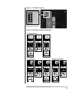
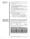
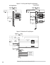
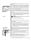
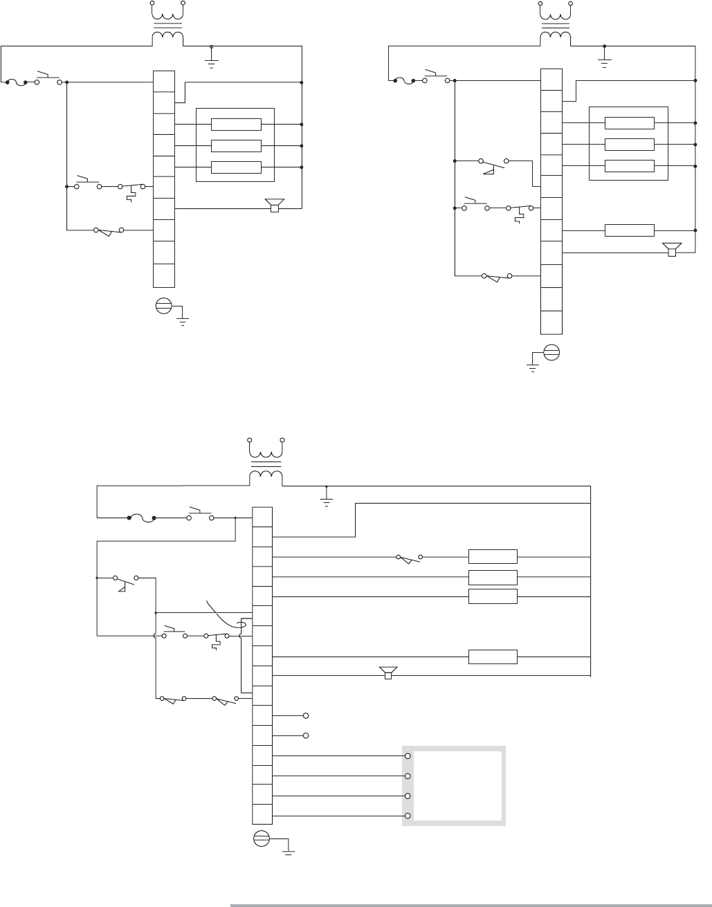
Figure 5.1
No Purge and Purge Wiring Diagrams
No Purge Models
Purge Models
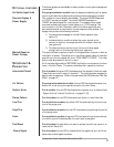
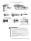
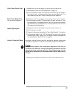
Figure 5.2
Modulation Wiring Diagram
On/Off
15 A
Fuse
7
S1
S2
V
1
2
Alarm
Interlocks & Limits
3
4
5
On/Off
15 A
Fuse
A
Piloted Burner
Pilot
Ignition
Main
Piloted Burner
Pilot
Ignition
Main
7
S2
S1
1
2
Alarm
Interlocks
& Limits
3
4
5
V
6
8
A
Fan
Air Flow Switch
Proof of Closure
5602/5605:
120 VAC
50/60 HZ
5603:
240 VAC
50/60 HZ
5602/5605:
120 VAC
50/60 HZ
5603:
240 VAC
50/60 HZ
Proof of
Closure
G
G
15 A. Fuse
6
7
8
A
10
11
12
13
D
S2
S1
High Fire
Low Fire
Automatic
Common
1
2
Flame
Sensor
Terminals
High Purge
Damper
Switch
Alarm
Interlocks
& Limits
Air Flow
Cut Red
Jumper
To Activate
Terminal D.
3
4
5
Low Fire Proving
Ignition
Pilot
Main
Fan
G
5602/5605:
120 VAC
50/60 HZ
5603:
240 VAC
50/60 HZ
On/Off
Proof of
Closure
See the “High to
Low Fire Purge
Modulation
Capability” section
on page 16 for
contact connections.