


18
Eclipse Veri-Flame Instruction Manual 818-2/02
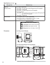
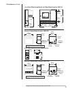
System Installation
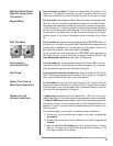
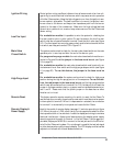
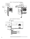
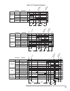
In this section, the necessary procedures are detailed to integrate a Veri-Flame into a
burner system; Figures 5.1 and 5.2 illustrate the various terminal strips mentioned.
Note:
Shut off the power supply before the Veri-Flame is removed or replaced from the base.
Caution:
Installation and maintenance must conform with the National Electrical Code and all
other national and local codes and authorities having jurisdiction. Flame monitoring
systems must be installed by a qualified, licensed technician.
For purge and modulation models: Wire any switches and contacts in
series to this terminal for proving air flow function and relating to the air failure
light. Power must not be immediately present at terminal 6 when power is first
applied to terminals 1 or 7.
If this terminal is not used, place a jumper between the combustion blower out-
put (terminal 8) and the air switch input (terminal 6).
If the combustion air blower is controlled outside of the Veri-Flame system, then
a three way solenoid valve must be connected between the air switch port and
the blower sensing port. The valve de-energized state should vent the switch
to ambient pressure. The energized state then connects the air switch to the
blower sensing port. Power the valve from the blower ouput terminal 8. If
accepted by local codes, the air switch could be wired between the combustion
blower output and the air switch input. Connecting the air switch in this man-
ner will satisfy the open contact (air short) check on the switch.
INTRODUCTION
Interlocks and
Limit Switch Input
Combustion Air
Switch Input
5
Wire external interlock, control, and limit switches in series to this input. Guard
against induced voltage levels to wiring connected to this input. In some extreme
wiring runs, reduction of induced voltages may require a load (relay or light) connected
to terminal 7 to avoid system error lockouts. This input is the power source for the
valve and ignition output terminals. Be sure all switches wired to this input can handle
the current required by the total of all loads connected to terminals 3, 4,and 5.