


17
Eclipse Veri-Flame Instruction Manual 818-2/02
S
TATUS
L
IGHTS
&
P
USH
-
BUTTON
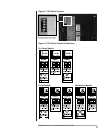
All of the status lights and the TEST/RESET push-button are located on the front
cover of the Veri-Flame. This section describes their respective functions.
For all models: this green LED illuminates when the operation limits are made.
These limits are wired in series to terminal 7. This input becomes energized to
begin the burner sequence. When in the test mode, this LED blinks (see “Pilot Test
Mode” on page 15).
For purge and modulation models: this red LED illuminates whenever com-
bustion air is lost during the operational cycle of the Veri-Flame.
For all models: this red LED illuminates when a system error is detected (see
“System Errors & Lockout Conditions” on pages 15-16).
For all models: this red LED illuminates when a pilot or main flame fails.
For modulation models: this yellow LED illuminates during the low fire pe-
riod of the purge cycle.
For modulation models: this red LED illuminates during the high fire period
of the purge cycle.
For modulation models: this green LED illuminates during the automatic pe-
riod which occurs 20 seconds after the main valve is energized.
For all models: this push-button is used to activate the pilot test mode or to
reset the Veri-Flame unit.
For all models: this red LED is located behind the signal test port and illumi-
nates when a flame signal is present.
Air Failure
System Error
Flame Failure
Low Fire
High Fire
Auto
Test/Reset
Flame Signal
Interlocks Closed
Manual Reset on
Power Outage
This optional feature requires a reset on initial application of power or after an
interuption of power. The system error light blinks rapidly (about 4 times per
second) and a remote display will show “PUSH RESET TO START”. The reset
button must be pressed in and out to start
The following features are available on select models, or when optional equipment
is purchased.
OPTIONAL FEATURES
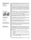
Remote Display &
Power Supply
Air Switch Input Hold
For purge/modulation models: holds the sequence indefinitely until air switch
input is confirmed without affecting the air failure function and causing a lockout.
Two models of remote display are available. The model 5602DB operates
on 24VDC and has no keypad. The model 5602DBP operates on
120VAC and has a keypad for reset function. The display is door panel
mounted and features a liquid crystal display in a ¼ DIN housing. The
unit connects to the Veri-Flame by a cable to the flame signal test jack,
and receives a serial communication on each sequence state change. The
display incorporates the following functions:
1) Provides status messages for the Veri-Flame sequence (see
section 9).
2) Indicates lockout conditions when they occur, as well as the
amount of time into the sequence when the lockout occurred
(see section 9).
3) Provides continuous monitoring of the burner’s flame signal
strength and run time during main burner operation.