


26
Eclipse Veri-Flame Instruction Manual 818-2/02
INTRODUCTION
Flame Signal Strength
Test Procedures
7
This section describes the test procedures that must be performed after instal-
lation to insure that the Veri-Flame is operating properly; these procedures are
mandatory.
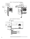
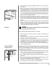
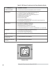
Insert the positive probe of
a 0-15 VDC, digital volt meter into the test
point on the front cover of the Veri-Flame; connect the negative probe to
ground. A good flame signal strength will read between 6 and 11 VDC; any-
thing below 4 VDC is inadequate. Also, the red LED inside the test point
illuminates when a flame signal is indicated.
Run the following test procedures to ensure that the sensor will not detect a
pilot flame too small to reliably light the main flame:
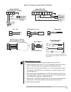
1) Manually shut off the fuel supply to the burner, but not to the pilot.
2) Start the system normally.
3) To enter the pilot test mode, depress the test/reset button located in the
lower right corner on the front cover.
4) The control will hold the operating sequence at the pilot flame step. Mea-
sure signal strength as described above.
5) Reduce pilot fuel until the flame relay drops out. Increase pilot fuel until the
flame signal is greater than 4 VDC, and flame relay just manages to pull in.
This is the minimum pilot. If you don’t think this flame will be able to safely
light the main burner, realign the sensor so that it requires a larger pilot
flame and repeat steps 2 through 5.
6) Push the test/reset button located in the lower right corner on the front cover
to exit the test mode (reset) and begin the normal start-up sequence again.
7) When the sequence reaches the main flame trial for ignition, smoothly re-
store the fuel supply to the burner. If the main burner does not light within
five seconds, immediately shut off the burner supply to shut down the sys-
tem. Realign the sensor so that it requires a larger pilot flame. Repeat steps
1 through 6 until the main burner lights off smoothly and reliably.
Minimum Pilot Test