


25
Eclipse Veri-Flame Instruction Manual 818-2/02
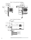
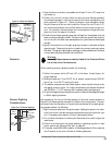
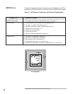
1) Keep the flame rod as short as possible and at least 13 mm (1/2") away from
any refractory.
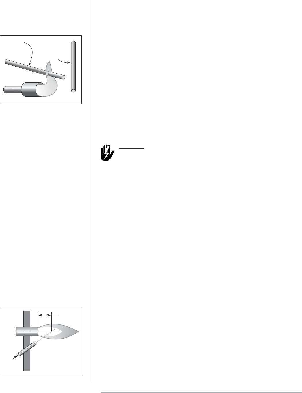
2) Position the rod into the side of both the pilot and main flames, preferably
at a descending angle to minimize drooping of the flame rod against burner
parts, as shown in Figure 6.1. Flame rod position must adequately detect
the pilot flame at all burner draft conditions. Extend the rod 13 mm (1/2")
into nonluminous flames, such as blue flames from burning an air/gas mix-
ture. For partially luminous flames, such as atmospheric air/gas mixtures,
place the rod at the edge of the flame.
3) Provide a burner/flame grounding area that is at least four times greater than the
flame rod area contacting the flame. The flame rod/burner ground ratio and posi-
tion of the rod in the flame may need adjustment to yield maximum flame signal
strength.
4) Ignition interference from the spark plug may increase or decrease the flame
signal strength. Reversing the ignition transformer primary leads may reduce
this effect. Changing the spark gap or adding grounding area between the flame
rod and spark plug may eliminate the interference.
Warning
Use only Eclipse scanner models as listed in the Illustrated Parts
List at the end of this document.
When installing scanners, please consider the following:
1) Position the scanner within 457 mm (18") of the flame. Consult factory for
longer distances.
2) Bushing threads are 1/2 inch F.N.P.T. for all scanner models except 5602-91
which has 1 inch F.N.P.T. bushing threads.
3) The ambient temperature limits of each scanner varies; check the literature for
the specific scanner model. For higher temperatures, use Eclipse heat block
seal 23HBS for ½” N.P.T. scanners and if necessary, add cooling purge air.
4) An optional magnifying lens may also be used to increase the flame signal strength
in difficult sighting situations.
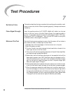
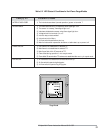
Aim scanners at the third of the flame closest to the burner nozzle, as shown in
Figure 6.2 (oil flames typically have less UV radiation in the outer flame). The scan-
ner should view the intersection of the pilot and main flames. When sighting scan-
ners, please consider the following:
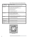
1) Sight the scanner away from the ignition spark. Sighting the spark or its reflec-
tions from burner internals can cause nuisance shutdowns during burner igni-
tion. If necessary, use a scanner orifice to reduce spark pickup.
2) Do not allow the scanner to detect a pilot flame that is too small to ignite the
main burner.
3) Perform a minimum pilot test when installing or adjusting any pilot or main
burner system; see “Minimum Pilot Test” on page 26.
4) I.R. scanner model 5600-92B is ideal for oil flame applications. When used, aim
the I.R. scanner at the outer oil flame for flickering detection.
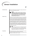
Scanners
Scanner Sighting
Considerations
WRONG
Rod Detects
Weak Pilot
PILOT
CORRECT
Rod Detects
Only Strong
Pilot Flame
Figure 6.1 Flame Rod Position
1/3 of
Flame Length
MAIN
BURNER
SCANNER
Scanner
Sight
Line
Figure 6.2 U.V. Scanner Sighting