


83
The PremierLinkt controller will generate a Linkage
Communication Failure alarm if a failure occurs for 5
consecut ive minutes once a Linkage has previously been
established. It will then revert back to its own SPT,
setpoints and occ upancy sche dule for control. For this
reason, Carrier strongly recommends that an SPT be
installed in the space on open plenum systems or in the
return air duct of ducted ret urn air systems to provide
continued backup operation. When Linkage
communication is restored, the controller will generate a
return to normal.
For more information on how the PremierLink controller
is used in conjunction with the Carrier 3V control system,
conta ct your CCN controls representative.
IMPORTANT: The PremierLink controller should not be
used as a linked air source in a ComfortIDt VAV system.
The ComfortID VAV system will NOT function correctly
when applied with a PremierLink controller as the air
source, resulting in poor comfort control and possible
equipment malfuncti on.
NOTE: The PremierLink controller can be used as an air
source in a 3V Pressure Independent (PI) System (a 3V
Linkage Coordinator with ComfortID PI Zone
Controllers), but it should not be used as an air source
with ComfortID controllers unless a 3V zone controller is
used as the L inkage Coordinat or. Contac t your Carrier
CCN controls representative for assistance.
Demand Limit — If the demand limit option is enabled,
the control will receive and accept Redline Alert and
Loadshed commands from the CCN loadshed controller.
When a redline alert is received, the control will set the
maximum stage of capacity equal to the stage of capacity
that the unit is operating at when the redline alert was
initiated.
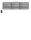
When loadshed command is received the control will
reduce capacity as shown in Table 32.
Table 32 – Loadshed Command — Gas and Electric
Heat Units
CURRENT CAPACITY NEW CAPACITY
CMP1 DX Cooling OFF
CMP1+CMP2 CMP1
HS1 Heat OFF
HS1+HS2 (+HS3) HS1
The controller will have a maximum demand limit timer
of 1 hour that prevents the unit from staying in load shed
or redline alert longer than 1 hour in the e vent the
controller loses communication with the network load
shed module. Should the maximum demand limit timer
expire prior to receiving the loadshed device command
from CCN, the control will stop demand limit mode and
return t o normal operation.
RTU--MP Sequence of Operation
The RTU--MP will control the compressor, economizer
and heating outputs based on its own space temperature
input and setpoints. An opt ional CO
2
IAQ sensor mounted
in the space can influence the economizer minimum
position. The RTU--MP has its own hardware clock that is
set automatically when the software is installed on the
board. The RTU--MP’s default is to control to occupied
setpoints all the time, until a type of occupancy control is
set. Occupancy types are described in the scheduling
section. The following sections descri be the operation for
the functions of the RTU--MP. All point objects that are
referre d to in this sequence will be in reference to the
objec ts as viewed in BACview
6
Handheld.
Scheduling
Scheduling is used to start heating or cooling (become
occupied) based upon a day of week and a time period and
control to the occupied heating or cooling setpoints.
Scheduling functi ons are located under oc cupancy
determination and the schedule menu accessed by the
Menu softkey (see Appendix -- for menu structure). Your
local time and date should be set for these functions to
operate properly. Five sc heduling functions are available
by changing the Occupancy Source to one of the
following selections:
Always Occupied (Default Occupancy)
The unit will run continuously. RTU--MP ships from the
factory with this setting.
Local Schedule
The unit will operate according to the schedule c onfigured
and stored in the unit. The local schedule is made up of
three hierarchy levels that consist of two Override
schedule s, twelve Holiday and four Daily schedules, and
are only accessible by the BACview screen (handheld or
virtual).
The Daily schedule is the lowest schedule in the hierarchy
and is overridden by both the Holiday and Override
schedule. It consists of a start time, a stop time (both in 24
hour mode) and the seven days of the week, starting with
Monday and ending in Sunday. To select a daily schedule
scroll to the Schedules menu off of the Menu selection.
Enter the User password and change the Occupa ncy
Source to Local Schedule. Sc roll down and over to the
Daily menu and press enter. Choose one of the four Daily
schedule s by pre ssing the Next softkey and change the
Use? point from NO to YES by selecting the point and
pressing the INCR or DECR softkey. Press the OK softkey
and scroll to the start and stop times. Edit these times
following the same steps as the Use? point. Finally scroll
down t o the Days: section and highlight the days required
for the Daily schedule by INCR or DECR softkeys and
press OK softkey.
48TC