


19
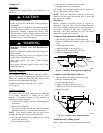
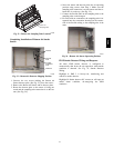
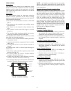
Return Air
Sampling Tube
C08129
Fig. 22 -- Return Air Sampling Tube Location
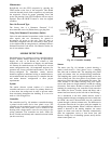
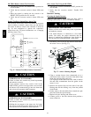
Completing Installation of Return Air Smoke
Sensor:
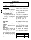
SCREWS
EXHAUST
TUBE
FLEXIBLE
EXTENSION
TUBE
SAMPLING
C08126
Fig. 23 -- Return Air Detector Shipping Position
1. Unscrew the two screws holdi ng the Return Air
Sensor detector plate. (See Fig. 23.) Save the screws.
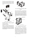
2. Remove the Return Air Sensor and i ts detector plate.
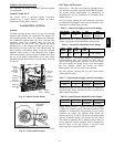
3. Rotat e the detector plate so the sensor is facing out-
wards and the sampling tube connection is on the bot-
tom. (See Fig. 24.)
4. Screw the sensor and detector plate into its operating
position using screws from Step 1. Make sure the
sampling tube connection is on the bottom and the ex-
haust tube is on the top. (See Fig. 23.)
5. Connect the flexible tube on the sampling inlet to the
sampling tube on the basepan.
6. For units with an economizer, the sampling tube is in-
tegra ted into the econom izer housing but t he connec-
tion of the flexible tubing to the sampling tube is the
same.
C08127
Fig. 24 -- Return Air Sensor Operating Position
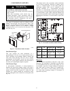
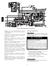
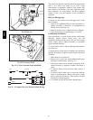
FIOP Smoke Detector Wiring and Response
All units: FIOP smoke detector is configured to
automatically shut down all unit operations when smoke
condition is detected. See Fig. 25, Smoke Detector
Wiring.
Highlight A: JMP 3 is factory--cut, transferring unit
control to smoke detector.
Highlight B: Smoke dete ctor NC contact set will open on
smoke alarm condition, de--energizing the ORN
conduct or.
48TC