


18
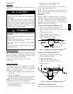
The sensor uses a process called differential sensing to
prevent gradual environmental changes from triggering
false alarms. A ra pid change in environmental conditions,
such as smoke from a fire, causes the sensor to signa l an
alarm state but dust and debris accumulated over time
does not.
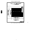
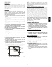
Duct smoke sensor
See
Detail A
Exhaust tube
Plug
Sampling tube
(ordered separately)
Intake
gasket
Cover gasket
(ordering option)
TSD-CO2
(ordering option)
Sensor housing
and electronics
Exhaust gasket
Coupling
Sensor cover
Detail A
Magnetic
test/reset
switch
Alarm
Trouble
Power
Dirty
C08209
Fig. 19 -- Smoke Dete ctor Sensor
For installations using two sensors, the duct smoke
dete ctor does not differentiate which sensor signals an
alarm or trouble condition.
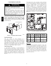
Smoke Detector Locations
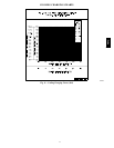
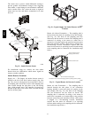
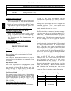
Supply Air — The Supply Air smoke detector sensor is
located to the left of the unit’s indoor (supply) fan. (See
Fig. 20.) Access is through the fan access panel. There is
no sampling tube used at this location. The sampling tube
inlet extends through the side plate of the fan housing
(into a high pressure area). The controller is located on a
bracket to the right of the return filter, accessed through
the lift--off filter panel.
Smoke Detector Sensor
C08245
Fig. 20 -- Typical Supply Air Smoke D etector Sensor
Location
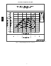
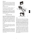
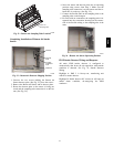
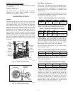
Return Air without Economizer — The sampling tube is
located across the re turn air opening on the unit basepan.
(See Fig. 21.) The hol es in the sampling tube face
downward, into the return air stream. The sampling tube is
connec ted via tubing to the return air sensor that is
mounted on a bracket high on the partition between return
filter and controller location. (This sensor is shipped in a
flat--mounting location. Installation requires that this
sensor be relocated to its operating location and the tubing
to the sampling tube be connected. See installation steps
below.)
Return Air Detector Sampling Tube
Controller module
Return Air Detector module
(shipping position shown)*
*RA detector must be moved from shipping position to operating position by installer
C07307
Fig. 21 -- Typical Return Air Detector Location
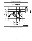
Return Air with Economizer — The sampling tube is
inserted through the side plates of the economizer
housing, placing it across the return air opening on the
unit basepan. (See Fig. 22.) The holes i n the sampling
tube face downward, into the return air stream. The
sampling tube is connected via tubing to the return air
sensor that is mounted on a bracket high on the partition
between return filter and controller location. (This sensor
is shipped in a flat--mounting location. Installation
requires that this sensor be relocated to its operating
loca tion and the tubing to the sampli ng tube be connected.
See installation steps below.)
48TC