


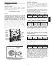
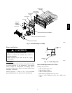
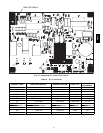

31
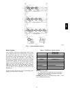
Red LED-Status
C08452
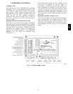
Fig. 39 -- Integrated Gas Control (IGC) Board
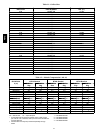
Table 10 – IGC Connections
TERMINAL LABEL POINT DESCRIPTION SENSOR LOCATION TYPE OF I/O
CONNECTION
PIN NUMBER
INPUTS
RT, C Input p ower from TRAN 1 control box 24 VAC —
SS Speed sensor gas section analog input J1, 1-3
FS, T1 Flame sensor gas section switch input —
W Heat stage 1 LCTB 24 V AC J2, 2
RS Rollout sw itch gas section switch inp ut J2, 5-6
LS Limit switch fan section switch inp ut J2, 7-8
CS Centrifugal switch (not used) — switch input J2, 9-10
OUTPUTS
L1, CM Induced draft combustion motor gas section line VAC
IFO Indoor fan control box relay J2, 1
GV Gas valve (h eat stage 1) gas section relay J2, 11-12
48TC